• Steel Soldiers now has a few new forums, read more about it at: New Munitions Forums!

  • Microsoft MSN, Live, Hotmail, Outlook email users may not be receiving emails. We are working to resolve this issue. Please add support@steelsoldiers.com to your trusted contacts.

Craig tulls drawing (003A)

Chainbreaker

Well-known member
1,802
2,010
113
Location
Oregon
Thanks Chainbreaker. I might be asking you some questions later on about this drawing.
Unfortunately, I never made a decision to convert any of my -002a units, yet that is, so I can't be of much help guiding you on using that drawing other than saying those are the wire #'s identified as to how the wires were hooked up on that Terminal Block he used.

I also had a mouse set up home in one of my trailered units AC reconnection boxes & and it took out my wiring as well. :mad: Though I was very fortunate I had bought a spare AC reconnection box a few years back that I had sitting on shelf ready to swap out with the bad one.

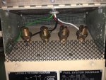
FYI: For those facing potential mouse problems on these models (-002a/-003a), I put some metal hardware cloth all the way back behind the load terminals (secured with screws) so that opening in back was mouse proof. I'm speculating that the ~1" opening in back is to allow ventilation for any heat created by the transformers, etc. to vent out so that's why I used hardware cloth.

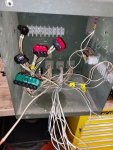
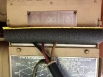
On my other 3 units I did a quick temporary "mouse deterrent fix" using 1" ID black pipe insulation tubes. I cut insulation to flap opening length & mounted lengthwise over flap lip to form a "C" & inserted in the opening where the wires enter the outside of the box & attach to load terminals. It conforms itself around the wires & seals up the opening pretty tightly. Though a determined mouse could chew through that stuff... however without the "enticing opening" or any smell of food inside there is not much motivation for a mouse to crawl up the side of box & chew through the foam. So far, it's working to keep mice out of my other 3 boxes. When I run those units, I temporarily remove the pipe foam to allow for heat dissipation if running for any length of time. I'll eventually retrofit those with hardware cloth or go the AVR retrofit route & get rid of the AC Reconnection box as you are in the process of & as others have done for reliability.

Also, setting out mouse traps near my generators has cut down on the mouse population but field mice always seem to send in reinforcements...🐭🐭🐭 so it's a constant battle when living in a rural area.

Below photo #3 shows how I used the pipe insulation foam sleeves on one of my generators AC reconnection boxes to deter mice from entering (the temp fix).

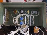
The other 2 photos show the install of the hardware cloth installed inside another generator's AC reconnection box that I have configured to exit out of the top of box to run wiring out to top of trailer bows & over to my onboard spider box. I also had some plastic gutter screen stuff laying around & decided to use to close off the flap gap to prevent mice from entering & building a nest by load terminals or chewing those wires. Though not very likely they would hang out by the load terminals, but I feel better knowing a "do not enter mice not welcome" barrier is up regardless.

Anyway, hope this helps others to mouse proof their -002a/-003a AC reconnection boxes if you're not doing a full on AVR conversion.
IMG_2571.jpgIMG_2571.jpgIMG_2572.jpgIMG_2573.jpgIMG_2571.jpgIMG_2572.jpgIMG_2573.jpgIMG_2571.jpg
 
Last edited:
178
16
18
Location
Jackson NJ
Good day and how are you all doing. Well, I bought an sx460 off amazon and that arrived. I ordered the Polarus connectors, still not here. So I was out in the garage last night stripping out the connection box from the 003a. So far I have the voltage selector switch out, ct1&cvt1 transformers out, a4 bridge rectifier out, and the Lineer ractor out. A whole mess of loose wires in there.
I do have a question though. If they are using 8ga wire from the alternator and up to the main breaker (cb1) then why from the breaker to the connection lugs did they change to a 4 ga. wire? if there is a reason can somebody chime in ?
Thanks, metalworker393
 

Scoobyshep

Well-known member
1,160
1,583
113
Location
Florida
Good day and how are you all doing. Well, I bought an sx460 off amazon and that arrived. I ordered the Polarus connectors, still not here. So I was out in the garage last night stripping out the connection box from the 003a. So far I have the voltage selector switch out, ct1&cvt1 transformers out, a4 bridge rectifier out, and the Lineer ractor out. A whole mess of loose wires in there.
I do have a question though. If they are using 8ga wire from the alternator and up to the main breaker (cb1) then why from the breaker to the connection lugs did they change to a 4 ga. wire? if there is a reason can somebody chime in ?
Thanks, metalworker393
Their specific reason couldnt tell you. Reasons it might be: type of insulation. might be a multi purpose part. Tap rule.
 
178
16
18
Location
Jackson NJ
It looks like he wired double delta, And the Polaris connector count is correct. If i had to venture a guess the 3 wires are instrumentation and AVR feed. It looks like it will work that way.

Your 003, did it loose the avr or did a winding fail? Another issue you might have is getting the reaction going, might need a field flash circuit.
Hey scoobyshep how are you. I had some time today I was out in the garage working on the connection box. So to my surprise, I did find something that may have caused the unit to stop making power.
My Polaris connectors are not here yet and I was looking at rustystuds drawing. I figured why not at least see how that would look tied into the terminal block since i had time on my hands. I found X1a8 has a break in the wire. Cant tell if it was chewed on but I think that may be the culprit. After trying to fit those wires (8ga) in there Im leaning on going with the Polaris when they get here.
 
178
16
18
Location
Jackson NJ
Next thing i would like to look into is instrumentation.
Im not planning on using the oem gauges as they fail too often for me. I have bought several over the years and a takeout gauge wasnt too expensive to buy, but the last time i did the price had gone up.
I found some inexpensive gauges on ebay that I think will work. I haven't decided to lay them out horizontally or vertically for each leg. I will be looking to install on the panel, 2 voltmeters, 2 ammeters ( they have their own transformer) and a new frequency meter. The new gauges are electronic and have their own backlight.
What I want to remove from the control cubicle- with new gauges for the AC side I would like to remove old vr, T1 transfomer, A3transducer, R1 relay, gauges M3, M4, M5, and switch S8. The machine will now be 240v only, have an automatic avr so no need for the R1 rheostat. No need for the S8 selector, that can go , The T1 transformer and A3 frequency transducer can go too as they will now be obsolete.
So what I do need to figure out is what wires do I need from the connection box to the control cubicle. What wires are now available to be used for other purposes. The new ammeter shows in the picture it has its own transformer . I will have to cut the wires and splice the transformers in the connection cubicle and re attach them to the meters in the control cubical. 2 ammeters x 2 wires ea. I now need 4 unused wires for that. The voltage meters- the same , 2 meters x 2 wires. Will need another 4 unused wires as I believe the connections will be made in the connection cubicle the run up to the new meters. Then, the frequency meter. I dont know or think its actually neccasary to have with an avr. But, I would like to have a meter there for that anyway while im doing this.
The panel itself in the control cubicle, i think I can order a piece of aluminum and transfer my holes for the engine instrumentation then cut new holes on the other side for the AC instrumentation after I decide the layout.
feel free to chime in and tell me what you think. Thanks, metalworker393
 

Scoobyshep

Well-known member
1,160
1,583
113
Location
Florida
Next thing i would like to look into is instrumentation.
Im not planning on using the oem gauges as they fail too often for me. I have bought several over the years and a takeout gauge wasnt too expensive to buy, but the last time i did the price had gone up.
I found some inexpensive gauges on ebay that I think will work. I haven't decided to lay them out horizontally or vertically for each leg. I will be looking to install on the panel, 2 voltmeters, 2 ammeters ( they have their own transformer) and a new frequency meter. The new gauges are electronic and have their own backlight.
What I want to remove from the control cubicle- with new gauges for the AC side I would like to remove old vr, T1 transfomer, A3transducer, R1 relay, gauges M3, M4, M5, and switch S8. The machine will now be 240v only, have an automatic avr so no need for the R1 rheostat. No need for the S8 selector, that can go , The T1 transformer and A3 frequency transducer can go too as they will now be obsolete.
So what I do need to figure out is what wires do I need from the connection box to the control cubicle. What wires are now available to be used for other purposes. The new ammeter shows in the picture it has its own transformer . I will have to cut the wires and splice the transformers in the connection cubicle and re attach them to the meters in the control cubical. 2 ammeters x 2 wires ea. I now need 4 unused wires for that. The voltage meters- the same , 2 meters x 2 wires. Will need another 4 unused wires as I believe the connections will be made in the connection cubicle the run up to the new meters. Then, the frequency meter. I dont know or think its actually neccasary to have with an avr. But, I would like to have a meter there for that anyway while im doing this.
The panel itself in the control cubicle, i think I can order a piece of aluminum and transfer my holes for the engine instrumentation then cut new holes on the other side for the AC instrumentation after I decide the layout.
feel free to chime in and tell me what you think. Thanks, metalworker393
Without scouring the diagrams, There should be enough existing wiring to accomplish that. really youll be replacing 1 gauge feed with another (freeing up a few in the process). Sounds like a solid plan, just make sure you dont cut out anything on the fuel/engine control
 
178
16
18
Location
Jackson NJ
Hello and how are you all doing . It's been a while since I had a chance to work on this .
I went back to work and my free time has been used doing everything else at the house and my job .
So, this is about as far as I managed to get on the job . If I have this correct, this should be for the 240v double delta connection.
I've identified the wires from J12 to TB 3 , 5&6. From TB3 to J11.
From there I need a little, okay alot of input getting inside the control cubicle.
I have a cubicle from a dismantled machine that's missing a few parts and I'm using it to get some bearing on what I have to change .
I'll be removing the frequency transducer, changing the voltmeter , frequency meter, percent load meter out for a digital replacement.
I've been looking through the manuals, and can't really find what transformers T1 and T2 do. I think T2 is tied into cvt1 or 2 and I m not sure about T1. If they were both used with cvt1 and 2, then I would like to take them out.
I have also been reading Rustystuds "modifying the MEP 002A and 003A generators "
Keep trying to figure out what he did inside the cubicle, and what he was able to get rid of .
I don't know, but I think he mounted the new avr in place of the old 1 and only used P60a16 and P59 . Anybody have any idea if that's correct ?
Thanks, metalworker393
 

Attachments

Top
AdBlock Detected

We get it, advertisements are annoying!

Sure, ad-blocking software does a great job at blocking ads, but it also blocks useful features of our website like our supporting vendors. Their ads help keep Steel Soldiers going. Please consider disabling your ad blockers for the site. Thanks!

I've Disabled AdBlock
No Thanks