jnlperformance
Member
- 71
- 2
- 8
- Location
- Atlanta, GA
Ok, so I have successfully isolated the ground for the cs130 alternator along with creating a cooling device and resistor just in case temps start to rise and the alt starts to blow... which im still expecting. the case has no ground connection. it checks out on a multimeter and "in theory" but electricity likes to do its own $hit sometimes lol.
i have not done anything about a "how to" on this matter yet because it may not work... BUT... i gotta try anyway.
just a quick overview (please correct me if im wrong);
the ground line on the 12v driver side is ok to ground through case and is to be mounted inbetween case and mount during alternator installation
ground on passenger side is derived from positive terminal on 12v(driver) and is mounted to modified isolated ground
12v driver charges one battery
12/24v passenger charges both batteries
now on to my question of the day... then after this i get to see if it works or not. does it catch fire? does it work? we shall see...
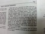
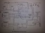
im going to include an excerpt out of the 94 series factory service manual for clarity on the function of the regulator and which terminals to hook up the brown and red wires from the origonal 27si harness connector. also going to post the cucv charging diagram as well.
ok... so hypothetically if one were to have converted to a serpentine belt system and CONVERTED from the 12/24 to direct 12v no 24... how would you wire up the 130 (if it were even used) were just talking about the regulator. the 27si has a 2 port regulator (much easier) the 130 has 4, which gives some room for error and a poof of smoke i dont want to see.
thankfully i can at least get somewhat of a reference from my 94. on that one the P and L terminals are the only ones used. the p goes to the tach and the L goes to ecm/voltmeter gauge.
from there I can derive...
P - for certian goes to tach wire lead (this part is NOT a question)
L - gauge set (brown wire on 6.2 harness - goes to gauge set) maybe??? this WOULD turn the alternator ON, but maybe thats only thru the use of an ECM
F/I - ?? to + junction block ?? (red wire on 6.2 27si harness - goes to + lead)
S - to + junction block ?? (red wire on 6.2 27si harness - goes to + lead)
so if you were just doing a 12v system on the cucv... where would the red wire from the 27si terminal go? F/I or S?


 sure did.