• Steel Soldiers now has a few new forums, read more about it at: New Munitions Forums!

  • Microsoft MSN, Live, Hotmail, Outlook email users may not be receiving emails. We are working to resolve this issue. Please add support@steelsoldiers.com to your trusted contacts.

CTIS pressure settings increase - no programming, transducer, or module required.

billyoffshore

New member
18
13
3
Location
Cape Charles, Virginia
WABCO ABS module is also on the J1939 although I haven't got one to speak over that bus - only via J1708. They will complain with an ABS light though if the bus is down. According to the schematic they are connected to both busses.

It is also possible in theory to connect the 260 amp alternator (it's voltage regulator anyway) used in the later trucks to to the J1939. I have successfully read voltage and RPM data from the VR on my truck. Niehoff has special software to get all the data from the VR including event logs. Pretty neat.
Gotcha……BTW, my ABS Light was “ON” when those resisters had failed. The ABS Light is Not Lit now, which is one of the tips you mentioned for me earlier…..thanks. I will detail Check that CTIS Harness, especially where it “taps in” on that J1939 wiring. Have a good Christmas and thank you for the help !
 

hike

—realizing each day
Steel Soldiers Supporter
540
854
93
Location
Texas Hill Country
Well, I (the other burnt resistor member) had an interesting experience today and was just coming in to make an M1078 CTIS schematic to M939A2 CTIS schematic.

Since replacing the resistors we have been using our plaza Arduino CTIS controller. Today while replacing the dash air brake hand controls I decided to swap our Dana/Spicer CTIS (the eBay M939A2 unit) and reprogram it to our preferred settings for Highway and Overland.

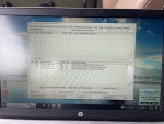
After installing the Dana/Spicer the ABS light returned. Hooking up our diagnostics the error codes in the trailer ABS system..

IMG_3789.jpeg

No other codes, J1939 sees other components, dynamic data reading.

Go ahead reprograming the Dana Spicer.

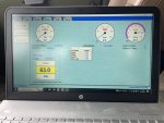
IMG_3793.jpeg

The reprogramming saves. After disconnecting diagnostics we test the new programs in the Dana/Spicer. Highway, the system inflates. Next Overland the system deflates. Almost to our Overland pressure the smell of burning plastic. The resistor under the PDP, and upon checking, the other near the fuel separator both fried.

Cleaned up, pulled the Dana Spicer out, ABS light back off again.

Planning to draw where the M1078A1 sends to CTIS and expects to receive next to what the M939A2 expects to receive and sends back while @billyoffshore explores the harness. Perhaps we'll find a way forward soon—
 
Last edited:

hike

—realizing each day
Steel Soldiers Supporter
540
854
93
Location
Texas Hill Country
WABCO ABS module is also on the J1939 although I haven't got one to speak over that bus - only via J1708. They will complain with an ABS light though if the bus is down. According to the schematic they are connected to both busses.

It is also possible in theory to connect the 260 amp alternator (it's voltage regulator anyway) used in the later trucks to to the J1939. I have successfully read voltage and RPM data from the VR on my truck. Niehoff has special software to get all the data from the VR including event logs. Pretty neat.
Ours seems to complain with an ABS light when the M939A2 Dana Spicer ECU is plugged in. Unplugging it turns off the ABS light. I believe the M939A2 CTIS ECU is sending something on a conflicting path for the M1078A1—
 

Brennan

New member
8
14
3
Location
Virginia Beach
I had the exact issue with the J1939 system,(stray 24v being dumped into data circuit). I ended up finding one of the junction points in the harness had rubbed into the 24v feed circuit for the blackout lights. I found this by attaching my meter to the J1939 wire with 24V and, one by one, removing circuit breakers from the PDP. Sure enough, once the culprit circuit breaker was removed, no more 24V was present on the data line. The data devices all came back online at that point.

I also found both the J1939 and J1708 wires to be in terrible shape, both would just crumble when you'd try to bare back the insulation. I ended up having to completely replace the wires with new shielded data link wire. Everything works perfect since then, knock on wood!
 

hike

—realizing each day
Steel Soldiers Supporter
540
854
93
Location
Texas Hill Country
Following up on the schematics.

It appears the M1078A1 and M939A2 wiring harnesses routed a few items differently at what appears to be the (M1078A1's P110) connector to the CTIS ECU.

Since @GeneralDisorder has suggested the Dana Spicer ECU's do not connect across J1939 and we can connect to our Dana Spicer using J1708; I am thinking IF using the M939A2 CTIS ECU in our M1078A1 we need to disconnect 'G'.

note: The plaza Arduino CTIS ECU does not connect to the J1939 circuit at all, ('G', 'W', 'X').

M939A2 DIFFERENCES
1— no diagnostic connections listed;
2— speed signals routed through 'Y' and 'K';
3— pressure switch 'B' also used, routed through 'L';
4— additional ground routed through 'V';
5— 'a', 'N', 'U', 'M' and 'A' not used.

CONFLICTS
The M939A2 CTIS ECU uses — M1078A1 uses:

'G' for the Control Switch 'A' — the M1078A1 routes control switch 'A' to ground through 'F' and uses 'G' for J1939 (+);
note: if you follow the M1078A1 J1939 (+) wire it does connect to R13 and R12.

'M' for the Wrecker Only Ground — the M1078A1 routes ground through 'F' and uses 'M' for optional power;

Should be OKAY?
The M939A2 CTIS ECU uses — M1078A1 uses:

'W' for the Control Switch 'B' — the M1078A1 routes control switch 'B' to ground through 'F' and uses 'W' for J1939 (shield);

'b' for the Pressure Transducer 'A' — the M1078A1 routes pressure transducer 'A' to common through 'j' and uses 'b' for power;
'j' for the Pressure Transducer 'B' — the M1078A1 routes pressure transducer 'B' to power through 'b' and uses 'j' for common;

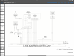
M939A2 schematic
IMG_3128.png

M1078A1 <18500 schematic
IMG_3129.jpeg


As I fried the last of my 120ohm resistors I'll have to await the arrival replacements, next up: to see if disconnecting 'G' may allow using the M939A2 CTIS ECU in our M1078A1 unit without conflicting with the J1939 system and causing a fault in the ABS system—
 
Last edited:

billyoffshore

New member
18
13
3
Location
Cape Charles, Virginia
Ours seems to complain with an ABS light when the M939A2 Dana Spicer ECU is plugged in. Unplugging it turns off the ABS light. I believe the M939A2 CTIS ECU is sending something on a conflicting path for the M1078A1—
Morning Hike; It is definitely interesting that we are both working on exactly the same issue, on the same day, on the same truck model, with the same purchased CTIS Controller. I truly thought I was going to have a Isolated incident with just our vehicle. One test for you that I had done so we can see if we are "both" getting the same symtoms:
1). Unplug that M939A2 unit and install the New resisters on the J1939 Cable.
2). Keep that CTIS Unit "Unplugged" and Battery Switch "OFF" Check that resistance with a DMM at the "D" and "C" pins on the DATA Port. ( CAN - & CAN +). Should be right at about 60 ohm of course.
3). Here is the interesting part I discovered: If I then plugged in that M939A2 CTIS unit, and Still had the Battery Switch OFF, that my DATA Port Readings on D (CAN -) and C (CAN +) went RIGHT to 3.9 ohm. NG.
4). When I did turn on the Battery Switch, and the Ignition main power at the dash, I got 24 volts on the D pin (CAN -). Also NG.
I didn't run the truck or the CTIS after seeing these readings. I think the results would be the same as yours for sure.
"Without" the M939A2 CTIS plugged in, I have perfect readings on the J1939 CAN Wiring. (Truck Running too, just CTIS Unplugged).
It's definitely that 24 volts on the CAN- Line that is Smoking those Resisters.
When I plug in my Original CTIS Unit, (which has ALL Lights lit sustained, and is NON Functioning, I do still have Perfect Readings on my J1939 DATA Port too.
It's definitely pointing towards an issue with how that M939A2 Unit is arranged. (I believe I had "exactly" the same results the first time I Plugged it in / Installed it, and put it thru it's functions, and it was on that "Deflate" from Highway, that it Smoked those Resisters).
Thanks for doing your follow up and response to my post! . It is actually "good news" (for both of us) that it seems to not be an Isolated issue with JUST our particular truck.
 

billyoffshore

New member
18
13
3
Location
Cape Charles, Virginia
I had the exact issue with the J1939 system,(stray 24v being dumped into data circuit). I ended up finding one of the junction points in the harness had rubbed into the 24v feed circuit for the blackout lights. I found this by attaching my meter to the J1939 wire with 24V and, one by one, removing circuit breakers from the PDP. Sure enough, once the culprit circuit breaker was removed, no more 24V was present on the data line. The data devices all came back online at that point.

I also found both the J1939 and J1708 wires to be in terrible shape, both would just crumble when you'd try to bare back the insulation. I ended up having to completely replace the wires with new shielded data link wire. Everything works perfect since then, knock on wood!
Morning....I have that SAME issue with those wires being "dry / brittle". I was JUST about to ask on here if someone had some luck routing a "Fresh" J1939 DATA CABLE and "Tapping on" at the four or 5 different points. I am guessing you own an "A1" truck with the 3126B ?
Following up on the schematics.

It appears the M1078A1 and M939A2 wiring harnesses routed a few items differently at what appears to be the (M1078A1's P110) connector to the CTIS ECU.

Since @GeneralDisorder has suggested the Dana Spicer ECU's do not connect across J1939 and we can connect to our Dana Spicer using J1708; I am thinking IF using the M939A2 CTIS ECU in our M1078A1 we need to disconnect 'G'.

note: The plaza Arduino CTIS ECU does not connect to the J1939 circuit at all, ('G', 'W', 'X').

M939A2 DIFFERENCES
1— no diagnostic connections listed;
2— speed signals routed through 'Y' and 'K';
3— pressure switch 'B' also used, routed through 'L';
4— additional ground routed through 'V';
5— 'a', 'N', 'U', 'M' and 'A' not used.

CONFLICTS
The M939A2 CTIS ECU uses — M1078A1 uses:

'G' for the Control Switch 'A' — the M1078A1 routes control switch 'A' to ground through 'F' and uses 'G' for J1939 (+);
note: if you follow the M1078A1 J1939 (+) wire it does connect to R13 and R12.

'M' for the Wrecker Only Ground — the M1078A1 routes ground through 'F' and uses 'M' for optional power;

Should be OKAY?
The M939A2 CTIS ECU uses — M1078A1 uses:

'W' for the Control Switch 'B' — the M1078A1 routes control switch 'B' to ground through 'F' and uses 'W' for J1939 (shield);

'b' for the Pressure Transducer 'A' — the M1078A1 routes pressure transducer 'A' to common through 'j' and uses 'b' for power;
'j' for the Pressure Transducer 'B' — the M1078A1 routes pressure transducer 'B' to power through 'b' and uses 'j' for common;

M939A2 schematic
View attachment 913437

M1078A1 <18500 schematic
View attachment 913438


As I fried the last of my 120ohm resistors I'll have to await the arrival replacements, to see if disconnecting 'G' may allow using the M939A2 CTIS ECU in our M1078A1 unit without conflicting with the J1939 system and causing a fault in the ABS system—
Thanks Hike....just saw this because I was typing here ! Great PDF's / Clear Pics there. Thanks so much. (I couldn't find a clear one of the M939A2 !).
 
Last edited:

hike

—realizing each day
Steel Soldiers Supporter
540
854
93
Location
Texas Hill Country
Morning Hike; It is definitely interesting that we are both working on exactly the same issue, on the same day, on the same truck model, with the same purchased CTIS Controller. I truly thought I was going to have a Isolated incident with just our vehicle. One test for you that I had done so we can see if we are "both" getting the same symtoms:
1). Unplug that M939A2 unit and install the New resisters on the J1939 Cable.
2). Keep that CTIS Unit "Unplugged" and Battery Switch "OFF" Check that resistance with a DMM at the "D" and "C" pins on the DATA Port. ( CAN - & CAN +). Should be right at about 60 ohm of course.
3). Here is the interesting part I discovered: If I then plugged in that M939A2 CTIS unit, and Still had the Battery Switch OFF, that my DATA Port Readings on D (CAN -) and C (CAN +) went RIGHT to 3.9 ohm. NG.
4). When I did turn on the Battery Switch, and the Ignition main power at the dash, I got 24 volts on the D pin (CAN -). Also NG.
I didn't run the truck or the CTIS after seeing these readings. I think the results would be the same as yours for sure.
"Without" the M939A2 CTIS plugged in, I have perfect readings on the J1939 CAN Wiring. (Truck Running too, just CTIS Unplugged).
It's definitely that 24 volts on the CAN- Line that is Smoking those Resisters.
When I plug in my Original CTIS Unit, (which has ALL Lights lit sustained, and is NON Functioning, I do still have Perfect Readings on my J1939 DATA Port too.
It's definitely pointing towards an issue with how that M939A2 Unit is arranged. (I believe I had "exactly" the same results the first time I Plugged it in / Installed it, and put it thru it's functions, and it was on that "Deflate" from Highway, that it Smoked those Resisters).
Thanks for doing your follow up and response to my post! . It is actually "good news" (for both of us) that it seems to not be an Isolated issue with JUST our particular truck.
Yes. The same issues, See this earlier post hunting for ABS solutions—
Well, of course it was not just R13 under the PDP; R12 near the Cat ECU is also looking like blackened redfish, in and out.

View attachment 910640

So, the question is since everything works, EXCEPT ABS do/did we have:
1— old resistors that died;
2— a bad ABS ECU;
3— a bare hot wire grounding out?

I am not confidant in my continuity testing, and I haven't tested anything at the ABS ECU; still we dropped new 120 ohm resistors in at R12 (I assume R12 is also a 120 ohm resistor?) and R13.

View attachment 910655

ABS light is OFF at the dash, I do not feel heat at either resistor, BUT the voltages at the Deutsch testing connection do not add up to less than 5.0v.

'D' should always be less than 2.5v, right?
View attachment 910652

'C'
View attachment 910653

We have 60 ohms between 'C' and 'D'.

View attachment 910654

What thoughts do we have? Over voltage by 15 hundreds, though everything appears to work. Headed out to plug in the DPA III+ to see if the J1939 side works now—
 

hike

—realizing each day
Steel Soldiers Supporter
540
854
93
Location
Texas Hill Country
Morning Hike; It is definitely interesting that we are both working on exactly the same issue, on the same day, on the same truck model, with the same purchased CTIS Controller. I truly thought I was going to have a Isolated incident with just our vehicle. One test for you that I had done so we can see if we are "both" getting the same symtoms:
1). Unplug that M939A2 unit and install the New resisters on the J1939 Cable.
2). Keep that CTIS Unit "Unplugged" and Battery Switch "OFF" Check that resistance with a DMM at the "D" and "C" pins on the DATA Port. ( CAN - & CAN +). Should be right at about 60 ohm of course.
3). Here is the interesting part I discovered: If I then plugged in that M939A2 CTIS unit, and Still had the Battery Switch OFF, that my DATA Port Readings on D (CAN -) and C (CAN +) went RIGHT to 3.9 ohm. NG.
4). When I did turn on the Battery Switch, and the Ignition main power at the dash, I got 24 volts on the D pin (CAN -). Also NG.
I didn't run the truck or the CTIS after seeing these readings. I think the results would be the same as yours for sure.
"Without" the M939A2 CTIS plugged in, I have perfect readings on the J1939 CAN Wiring. (Truck Running too, just CTIS Unplugged).
It's definitely that 24 volts on the CAN- Line that is Smoking those Resisters.
When I plug in my Original CTIS Unit, (which has ALL Lights lit sustained, and is NON Functioning, I do still have Perfect Readings on my J1939 DATA Port too.
It's definitely pointing towards an issue with how that M939A2 Unit is arranged. (I believe I had "exactly" the same results the first time I Plugged it in / Installed it, and put it thru it's functions, and it was on that "Deflate" from Highway, that it Smoked those Resisters).
Thanks for doing your follow up and response to my post! . It is actually "good news" (for both of us) that it seems to not be an Isolated issue with JUST our particular truck.
Thinking about how everything lines up and wishing to minimize changes to the M1078A1's wiring harness I decided to pull the 'G', 'W', and 'X' pins from the M939A2 CTIS ECU connector. Once I had pulled all three (matching the plaza Arduino CTIS, too) the ABS fault code dropped, and our diagnostics on both J1939 (not CTIS) and J1708 all work. Once we receive the new resistors we'll recheck the system voltages and ohms.

Being a rainy day here I took her out on a country road and tested the ABS system. Not sure I felt pluses in the pedal, though hammering the brakes at speed with nothing in the back didn't put us in a skid on a slick road. They are likely working or not yet needed.

Hopefully, isolating the M939 CTIS ECU from the J1939 system will be all we need. Since we have all the diagnostic equipment and have reprogrammed our Dana Spicer unit as we prefer I think I'll drop the multiple program route for now—
 

billyoffshore

New member
18
13
3
Location
Cape Charles, Virginia
Thinking about how everything lines up and wishing to minimize changes to the M1078A1's wiring harness I decided to pull the 'G', 'W', and 'X' pins from the M939A2 CTIS ECU connector. Once I had pulled all three (matching the plaza Arduino CTIS, too) the ABS fault code dropped, and our diagnostics on both J1939 (not CTIS) and J1708 all work. Once we receive the new resistors we'll recheck the system voltages and ohms.

Being a rainy day here I took her out on a country road and tested the ABS system. Not sure I felt pluses in the pedal, though hammering the brakes at speed with nothing in the back didn't put us in a skid on a slick road. They are likely working or not yet needed.

Hopefully, isolating the M939 CTIS ECU from the J1939 system will be all we need. Since we have all the diagnostic equipment and have reprogrammed our Dana Spicer unit as we prefer I think I'll drop the multiple program route for now—
Gotcha....thanks for the Update !..........We also do want to minimize changes on our M1078A1 Harness too. Quick question: Did you get the Highway pressure up to 80 PSI ? (or changed to what you wanted?) on the M939A2 ? Also, is the "plaza Arduino CTIS Unit on the Forum here ? I was just about to look it up and read about it. Do you like it?
and,
Hey, Hike.......Have a Good Christmas and New Years! Thanks for the info !
BTW, I used: buydeutsch.com (Nice Product Selection and Real Deutsch and good $$ & shipping).
 

GeneralDisorder

Well-known member
Steel Soldiers Supporter
2,124
5,407
113
Location
Portland, OR
It is true that the older CTIS control boxes don't coms with J1939. The newer FMTV ones do, but the older green box units and even the older black box units do not and since the 900 series trucks are older also I would not expect that they are capable of operating on J1939 anyway - so it may be that these boxes are not compliant to the specification laid out in the Dana troubleshooting guide. If removing the J1939 pins is all it takes to make them operate then I would say that's a win!
 

Lostchain

Well-known member
Steel Soldiers Supporter
285
590
93
Location
Portland, OR
Morning Hike; It is definitely interesting that we are both working on exactly the same issue, on the same day, on the same truck model, with the same purchased CTIS Controller. I truly thought I was going to have a Isolated incident with just our vehicle. One test for you that I had done so we can see if we are "both" getting the same symtoms:
Yes this is a super interesting problem.

Have you tried measuring resistance between G & X to F and G&X to H at the truck side of the CTIS connector with the controller disconnected ?
 
Last edited:

hike

—realizing each day
Steel Soldiers Supporter
540
854
93
Location
Texas Hill Country
Gotcha....thanks for the Update !..........We also do want to minimize changes on our M1078A1 Harness too. Quick question: Did you get the Highway pressure up to 80 PSI ? (or changed to what you wanted?) on the M939A2 ? Also, is the "plaza Arduino CTIS Unit on the Forum here ? I was just about to look it up and read about it. Do you like it?
and,
Hey, Hike.......Have a Good Christmas and New Years! Thanks for the info !
BTW, I used: buydeutsch.com (Nice Product Selection and Real Deutsch and good $$ & shipping).
It is true that the older CTIS control boxes don't coms with J1939. The newer FMTV ones do, but the older green box units and even the older black box units do not and since the 900 series trucks are older also I would not expect that they are capable of operating on J1939 anyway - so it may be that these boxes are not compliant to the specification laid out in the Dana troubleshooting guide. If removing the J1939 pins is all it takes to make them operate then I would say that's a win!
It is a win assuming we keep our resistors healthy.

The M939A2CTIS ECU (black) we received from a link @GeneralDisorder shared (thank you General) I believe is NOS. Came boxed and wrapped, still looks brand new.

IMG_2906.jpeg

We originally saw 55# highway pressure. The unit connects right up to the DPA III+ we have through the left knee connector and we set the speeds and pressures as we wished using the Dana Spicer software.

We like the Arduino CTIS ECU @Plasa (I have been miss typing) builds very much. It is plug and play, easy to program, does not conflict with our other systems, and it shares the status of the wet tank, PCU solenoids, which mode (terrain) you are at or heading to, and if you watch through the cycle you can see what the average pressure in the system is briefly. My only challenge is with my vision it is difficult to check status or change modes while driving. Others have commented that it is difficult to troubleshoot and not as robust. I am grateful to have it and on an less perfect CTIS it will likely work when the Dana Spicer goes to 5 flashing—
 

hike

—realizing each day
Steel Soldiers Supporter
540
854
93
Location
Texas Hill Country
Ran out and checked resistance between 'F' (ground) and 'B', 'C', and 'R' (inflate, deflate and control) all 64ohms; between 'H' (power) and 'B', 'C', and 'R' (inflate, deflate and control) all 150ohms.

@Lostchain what were you expecting?

edit: l'll try that—
re edit: my resistors are blown so, not going to be useful. I'll try to remember once all back in when I retest—
 
Last edited:

Lostchain

Well-known member
Steel Soldiers Supporter
285
590
93
Location
Portland, OR
Ran out and checked resistance between 'F' (ground) and 'B', 'C', and 'R' (inflate, deflate and control) all 64ohms; between 'H' (power) and 'B', 'C', and 'R' (inflate, deflate and control) all 150ohms.

@Lostchain what were you expecting?

edit: l'll try that—
re edit: my resistors are blown so, not going to be useful. I'll try to remember once all back in when I retest—

Yeah sorry about originally mentioning the wrong Pins, I lost track of which connector I was looking at for the J1939 data pins. I think whether you have resistors on there or not, there should be absolutely no connectivity between the power/ground (F&H) and Data (G&X). I guess that you would see problems on the data bus whether or not the CTIS was plugged in if the harness was bad, so maybe I'm barking up the wrong tree.
 

billyoffshore

New member
18
13
3
Location
Cape Charles, Virginia
Yeah sorry about originally mentioning the wrong Pins, I lost track of which connector I was looking at for the J1939 data pins. I think whether you have resistors on there or not, there should be absolutely no connectivity between the power/ground (F&H) and Data (G&X). I guess that you would see problems on the data bus whether or not the CTIS was plugged in if the harness was bad, so maybe I'm barking up the wrong tree.
That was Actually a thought that I had as well. (If the Harness had some sort of “short” or grounded wiring, I would get the same activity whether the M939A2 CTIS was plugged in, or Unplugged). One thing for certain is if the Battery switch is Off, and that CTIS was plugged in, my J1939 CAN line went right to only 3.9 oHm. (Testing it right at the DATA Service Plug on “D” and “C”. With that CTIS detached, it was a Perfect 60 oHm. Hike’s research and conclusion is “Right On” I think ! Have a Good Christmas Bud ! 77519B4C-8AF8-4252-95E7-AFB1BEF04EA3.jpeg
 

hike

—realizing each day
Steel Soldiers Supporter
540
854
93
Location
Texas Hill Country
Yeah sorry about originally mentioning the wrong Pins, I lost track of which connector I was looking at for the J1939 data pins. I think whether you have resistors on there or not, there should be absolutely no connectivity between the power/ground (F&H) and Data (G&X). I guess that you would see problems on the data bus whether or not the CTIS was plugged in if the harness was bad, so maybe I'm barking up the wrong tree.
All good. You all likely no better than I. I got 0 ohms for the 'G' and 'X' tests at the P110 connector to the CTIS ECU—
 

billyoffshore

New member
18
13
3
Location
Cape Charles, Virginia
Yes. The same issues, See this earlier post hunting for ABS solutions—
Good Morning Hike; Just so you have another trucks readings to compare:
Our "D" Voltage was "a bit" over that 2.5 too like yours (2.58v)
Our "C" Voltage was Very Similar at (2.66v).
Also, our Overall ohms between D & C are Right with yours almost at 59.1 as well.
This is of course with the M939A2 Unit NOT Plugged in.
It gives me confidence that we have matching Readings on our J1939's.
I am planning to "replace" our J1939 Cable Completely though. Not because of issues with the Readings, but because of how Dry and Brittle the actual Green and Yellow wires were, inside that cable. I don't want a "short" or Grounding in the future to do damage to anything. 21 years old, for both of us on the trucks. Our truck "looks New/ One month old" in so many areas. Just Not used.
Have a Good Christmas.
 
Top
AdBlock Detected

We get it, advertisements are annoying!

Sure, ad-blocking software does a great job at blocking ads, but it also blocks useful features of our website like our supporting vendors. Their ads help keep Steel Soldiers going. Please consider disabling your ad blockers for the site. Thanks!

I've Disabled AdBlock
No Thanks