• Steel Soldiers now has a few new forums, read more about it at: New Munitions Forums!

  • Microsoft MSN, Live, Hotmail, Outlook email users may not be receiving emails. We are working to resolve this issue. Please add support@steelsoldiers.com to your trusted contacts.

CTIS

Good morning,

I have a 1998 M1088A0 with a CTIS issue—go figure. The ECU is flashing 5 lights.

This site has assisted a bit in initial troubleshooting by providing the Dana troubleshooting guide as well as the TMs.

Doing the first couple of steps in the TM lead me to an electrical issue. Why? There are no bursts of air at port C on the manifold.

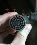
One thing I want to put out there is this: someone has been in the ECU plug/harness before me. What I found were two wires twisted together just behind the plug. That wire appears to be connected to pin Z. See pics. Looking at the face of the plug, there are only 15 pins in the pin slots…leaving a handful empty. Looking at the harness going into the back of the plug, there are only 14 wires. I stripped like 6” of insulation hoping to find a snipped wire and see no evidence of a 15th wire. So, there is one snipped wire on the back of the plug doing nothing.

Ideas?

Thanks.

John

F9A5FABB-4E42-446B-A67E-E40CB87CD0CB.png
 
Last edited:

coachgeo

Well-known member
5,150
3,466
113
Location
North of Cincy OH
Good morning,

I have a 1998 M1088A0 with a CTIS issue—go figure. The ECU is flashing 5 lights.

This site has assisted a bit in initial troubleshooting by providing the Dana troubleshooting guide as well as the TMs.

Doing the first couple of steps in the TM lead me to an electrical issue. Why? There are no bursts of air at port C on the manifold.

One thing I want to put out there is this: someone has been in the ECU plug/harness before me. What I found were two wires twisted together just behind the plug. That wire appears to be connected to pin Z. See pics. Looking at the face of the plug, there are only 15 pins in the pin slots…leaving a handful empty. Looking at the harness going into the back of the plug, there are only 14 wires. I stripped like 6” of insulation hoping to find a snipped wire and see no evidence of a 15th wire. So, there is one snipped wire on the back of the plug doing nothing.

Ideas?

Thanks.

John

View attachment 904336
this thread will help you learn how others brighter than I have used the TM schematic to trace wires.


Ronmar

Well-known member
3,884
7,549
113
Location
Port angeles wa
If Z was the free wire twisted with the other wire, I suspect it was twisted with the wire going to pin H(24V)? One way they made these units compatible with different vehicles is by how power is applied to the controller Via the harness. There are at least 3 different pins that can accept power. I suspect the way power is applied determines what programming is run. That way one controller with different programming could service different vehicles, by the configuration of the harness used in the different vehicles, such as timing or pressure differences between a 4X4 and a 6X6 tractor. This may have been a case of a motor pool madman adapting a harness from a different truck and reconfiguring it to the truck it was installed in.

this system uses a switch, pressure sensor and a stopwatch to control the air filled bombs we call tires. Because of the hazards I believe it relies heavily on time to make its decisions. 5 flashing usually means it did not see a proper result in the time it had available. This is usually the result of tires at radically different pressure or a leak.

a basic cycle goes sort of like this.
Pressure check:
1. Check atmospheric pressure on sensor.
2. Wet tank sw closes at 117PSI.
3. Close control solenoid on the PCU to seal system.
4. Give a shot of PCU supply solenoid air to pressurize system down thru the dump valves.
5. The dump valves mimic whatever is on their input/PCU side port and pass it to the wheel valves.
6. Wheel valves go over ~6 PSI they open and connect tires to the system.
7. Tire pressures equalize.
8. Controller notes difference from atmospheric test and looks for steady tire pressure.
9. Compare measured pressure with lookup table pressure stored for selected mode
10. Pressure low, initiate fill, pressure high, initiate deflate, pressure OK, release control. Control opening vents PCU air thru floor port behind grill which drops PCU pressure to 0. Dump valves see input from PCU at 0PSI and they vent their output to 0. Wheel valves seeing less than ~5 PSI on their input side close. This causes a brief dump valve vent. The system waits for next scheduled test.

Fill:
1. perform pressure check.
2. If low, open supply valve until wet tank sw opens at 89PSI then close supply.
3. Check pressure while waiting for wet tank switch.
4. When wet tank sw closes at 117 PSI, open supply.
5. Repeat 2-4 until pressure check shows correct pressure then open control to vent system(causes brief dump valve vent).

Deflate:
1. Perform pressure check.
2. If high, open deflate solenoid. The def solenoid connects the PCU to atmosphere via a 6.5 PSI relief valve. This acts as a regulator and drops the manifold pressure to 6-7 PSI. The dump valves copy this on their output by venting output air to atmosphere. 6-7PSI is enough to keep the wheel valves open, so the greater pressure in the tires flows back to the dump valves which continue to vent trying to match that 6-7PSI PCU/inlet ppressure.
3. After set time, close deflate solenoid and briefly open supply to pressurize system and perform pressure check.
4. Repeat 2-3 untill mode pressure is reached then open control solenoid to vent system and close wheel valves(brief dump valve vent).

Every one of these processes has a time limit attached, and the controller is expecting to see a very specific response. During the pressure check it is expecting to see a stable pressure after a very short time. A tire at a different pressure will still be equalizing and may cause it to fault As the pressure will still be changing. After an inflate cycle, it is expecting to see some form of pressure increase, and again a stable pressure. after a deflate it is expecting to see a pressure decrease and again a stable pressure.

it does this to know that it has control, and will fault at the drop of a hat if it remotely suspects that it does not…
 
Last edited:
this thread will help you learn how others brighter than I have used the TM schematic to trace wires.

Thanks for the info!
 
If Z was the free wire twisted with the other wire, I suspect it was twisted with the wire going to pin H(24V)? One way they made these units compatible with different vehicles is by how power is applied to the controller Via the harness. There are at least 3 different pins that can accept power. I suspect the way power is applied determines what programming is run. That way one controller with different programming could service different vehicles, by the configuration of the harness used in the different vehicles, such as timing or pressure differences between a 4X4 and a 6X6 tractor. This may have been a case of a motor pool madman adapting a harness from a different truck and reconfiguring it to the truck it was installed in.

this system uses a switch, pressure sensor and a stopwatch to control the air filled bombs we call tires. Because of the hazards I believe it relies heavily on time to make its decisions. 5 flashing usually means it did not see a proper result in the time it had available. This is usually the result of tires at radically different pressure or a leak.

a basic cycle goes sort of like this.
Pressure check:
1. Check atmospheric pressure on sensor.
2. Wet tank sw closes at 117PSI.
3. Close control solenoid on the PCU to seal system.
4. Give a shot of PCU supply solenoid air to pressurize system down thru the dump valves.
5. The dump valves mimic whatever is on their input/PCU side port and pass it to the wheel valves.
6. Wheel valves go over ~6 PSI they open and connect tires to the system.
7. Tire pressures equalize.
8. Controller notes difference from atmospheric test and looks for steady tire pressure.
9. Compare measured pressure with lookup table pressure stored for selected mode
10. Pressure low, initiate fill, pressure high, initiate deflate, pressure OK, release control. Control opening vents PCU air thru floor port behind grill which drops PCU pressure to 0. Dump valves see input from PCU at 0PSI and they vent their output to 0. Wheel valves seeing less than ~5 PSI on their input side close. This causes a brief dump valve vent. The system waits for next scheduled test.

Fill:
1. perform pressure check.
2. If low, open supply valve until wet tank sw opens at 89PSI then close supply.
3. Check pressure while waiting for wet tank switch.
4. When wet tank sw closes at 117 PSI, open supply.
5. Repeat 2-4 until pressure check shows correct pressure then open control to vent system(causes brief dump valve vent).

Deflate:
1. Perform pressure check.
2. If low, open deflate solenoid. The def solenoid connects the PCU to atmosphere via a 6.5 PSI relief valve. This acts as a regulator and drops the manifold pressure to 6-7 PSI. The dump valves copy this on their output by venting output air to atmosphere. 6-7PSI is enough to keep the wheel valves open, so the greater pressure in the tires flows back to the dump valves which continue to vent trying to match that 6-7PSI PCU/inlet ppressure.
3. After set time, close deflate solenoid and briefly open supply to pressurize system and perform pressure check.
4. Repeat 2-3 untill mode pressure is reached then open control solenoid to vent system and close wheel valves(brief dump valve vent).

Every one of these processes has a time limit attached, and the controller is expecting to see a very specific response. During the pressure check it is expecting to see a stable pressure after a very short time. A tire at a different pressure will still be equalizing and may cause it to fault As the pressure will still be changing. After an inflate cycle, it is expecting to see some form of pressure increase, and again a stable pressure. after a deflate it is expecting to see a pressure decrease and again a stable pressure.

it does this to know that it has control, and will fault at the drop of a hat if it remotely suspects that it does not…
Answering your question...Pin Z was twisted with a wire in the harness...it didn't get joined to another pin on the plug end. Pin L on the plug is actually snipped at the back of the plug and is going nowhere.

Also, thanks for the other information. I will have to chew on that after work. By the way, I watched every one of your awesome YouTube videos on these machines. I appreciate them!

According to the TM, the test for the air on port C drove next steps of looking for an electrical issue. With someone being in the plug before me, I was hoping for something swift. If just baffles me that there are only 14 wires behind the plug but 15 pins look like they are "active." That single snipped wire (pin L) is somewhat suspect.

John
 

Ronmar

Well-known member
3,884
7,549
113
Location
Port angeles wa
Yea the wire pin z was twisted with is probably ultimately connected to H. If so it will have 24v on it with switch on. It was probably the wire L was originally connected to. I will have to lookup what L is used for this afternoon to confirm, but on the 1078 schematic I believe L was connected to the same power source as H
 
Last edited:
Yea the wire pin z was twisted with is probably ultimately connected to H. If so it will have 24v on it with switch on. It was probably the wire L was originally connected to. I will have to lookup what L is used for this afternoon to confirm, but on the 1078 schematic I believe L was connected to the same power source as H
Understood—thanks.
 

Ronmar

Well-known member
3,884
7,549
113
Location
Port angeles wa
I was mistaken. L is not listed on any documentation I have. H, M, Z are the indicated power inputs, shown in the manuals. Those 3 pins would give you 7 possible configurations to control programming. It shows H and Z connected on the 1078A0 manual.
 

Ronmar

Well-known member
3,884
7,549
113
Location
Port angeles wa
So when you say no bursts of air at port "C", What exactly are you identifying as port C? The port on the side of the plastic cover?
 

GeneralDisorder

Well-known member
Steel Soldiers Supporter
2,076
5,309
113
Location
Portland, OR
Lets start with basics.

First - lets assume (I know.... but for the sake of some simple checks) that someone screwed with the wiring to try to hookup to the unit and communicate because A0 trucks don't have coms ports - they are supposed to use a breakout cable that's never around when you need it......

Second - what is your wet tank pressure at compressor unload? If it's not high enough then the CTIS controller will not do anything and eventually fault out with 5 flashing lights and throw a pressure switch code.

Ronmar posits an interesting theory on the multiple maps depending on how you power the unit..... though I would *think* this would show up as options in the Dana Diagnostics software or instructions which it most definitely does not. So I kind of doubt this is a thing - also I've read multiple reports of people simply swapping in controllers from the trucks with higher pressure set points and having them work at the higher pressure which would seem to indicate that the truck wiring is the same on both applications and it's the module programming that's different.
 

Ronmar

Well-known member
3,884
7,549
113
Location
Port angeles wa
Ok, now I am tracking. You can control the 3 solenoid valves and the pcu function with a pair of jumper wires at the controller connector.

Pin H should have 24V with the switch on.
Pin R feeds the control solenoid.
Pin B feeds the air supply solenoid.
Pin C feeds the deflate solenoid.

Disconnect the connector from the controller and With the ign sw on, if you jumper pin H to R or B or C you shoukd hear the solenoids click in the PCU. If the wet tank is over 85 PSI, jumping B should also deliver air from the air supply.

To work the system:
Start the truck, fill the air tanks and shutdown the engine.
Take 2 jumper wires and twist one end of each together to form a V. Install the point of the V into pin H in the ctis controller connector.
Install one jumper leg from H-R and turn on the ign sw. This should close the control solenoid.
With the second leg of the V jumper, jump H to B briefly(1sec) to give a short shot of air to pressurize the system. You should be able to hear the air flow...

If you wait to long to give a shot of air after you close control, the system may start to dump tire air. Every PCU I have played with will slowly pressurize once control is closed. Once it rises over the ~6 PSI wheel valve pressure, it will start dumping the tires... It may have been designed like this to alert an operator to a shorted control solenoid circuit...

If your plumbing is sound this should open the wheel valves and the entire system should set at wheel pressure untill you remove power from pin R by pulling that jumper or turning off the ign sw.

If you have a leak, the pressure in the system will drop and the dump valves will start venting tire air to match the system pressure. Hopefully any leak will not be too bad and you will have some time to find it, or you must give a shot of air to bump system pressure up to stop the tire dump. You only get a few shots of air out of the wet tank.

Once the wet tank drops to 85PSI, it can not deliver anymore air to CTIS and you will have to refill the tank, either by connecting an external air source or briefly starting the engine. It is way easier to find leaks with the engine off.

DO NOT LEAVE SUPPLY SOLENOID JUMPERED/ON as this can fill tires to unsafe levels With engine running.

If you look at my utube channel under username rronmar, you can see me controlling the 3 solenoid valves in the PCU with 3 pushbuttons in my first CTIS video...
 

Ronmar

Well-known member
3,884
7,549
113
Location
Port angeles wa
Ronmar posits an interesting theory on the multiple maps depending on how you power the unit..
different harnesses in different vehicles has been documented. I think Sean even covered it in a video. The A1 wiring diagram shows this with 3 power inputs, an some being listed as "optional" which indicates some sort of option:)

at any rate his appears to be configured at least like the A0 and A1 diagrams with H and Z receiving power. Have found nothing to show what purpose L could posdibly serve. It looks as if that harnes was modified(poorly) to fit this application...

Wet tank pressure is a good check, it won't start a check without it, but I am not sure if it will time out to a 5 flash if it never closes/goes above 117PSI...

Another possibility is the pressure sensor on the PCU is fouled, and it never gets past seeing atmospheric pressure so never starts the test. They mounted it pointing straight up which is generally considered poor form...

Or he has a wiring issue and it cannot sense pressure or control the solenoids...
 

GeneralDisorder

Well-known member
Steel Soldiers Supporter
2,076
5,309
113
Location
Portland, OR
My truck had an incorrectly set unloader and the CTIS controller reported a pressure switch malfunction. My switch was fine the system just wasn't reaching the pressure set point. Controller can only assume the switch is bad
 

Ronmar

Well-known member
3,884
7,549
113
Location
Port angeles wa
My truck had an incorrectly set unloader and the CTIS controller reported a pressure switch malfunction. My switch was fine the system just wasn't reaching the pressure set point. Controller can only assume the switch is bad
Well it wasnt wrong, you did indeed have a issue with the wet tank switch circuit, not enough airpressure to close it:)

That has been a fairly common CTIS issue, low governor setpoint... i dont recall if it causes 5 flash though, did yours?
 

GeneralDisorder

Well-known member
Steel Soldiers Supporter
2,076
5,309
113
Location
Portland, OR
Well it wasnt wrong, you did indeed have a issue with the wet tank switch circuit, not enough airpressure to close it:)

That has been a fairly common CTIS issue, low governor setpoint... i dont recall if it causes 5 flash though, did yours?
I can't recall..... It may after a period of time or after it sees enough vehicle speed for enough elapsed time.

I just figured it's a good first check since the controller won't really do anything till it sees enough system pressure so no sense messing with the wiring till you determine that.

Also the Dana Diagnostic tool can command the system to perform any function - check pressure, vent, fill, etc. Very easy to use and the software is free. If I had an A0 I would build the necessary cable to interface the module or just get the Arduino unit from Plasa.
 

Ronmar

Well-known member
3,884
7,549
113
Location
Port angeles wa
I can't recall..... It may after a period of time or after it sees enough vehicle speed for enough elapsed time.

I just figured it's a good first check since the controller won't really do anything till it sees enough system pressure so no sense messing with the wiring till you determine that.

Also the Dana Diagnostic tool can command the system to perform any function - check pressure, vent, fill, etc. Very easy to use and the software is free. If I had an A0 I would build the necessary cable to interface the module or just get the Arduino unit from Plasa.
If I worked on them everyday, having the interface would be handy, but for a basic DIY troubleshoot, it is just as easy to jump the pins to control the PCU and test valve function and pressurize the system to look for leaks. Leaks are the usual issue with CTIs anyway… You can probe the sensor line and monitor the voltage feedback to gauge pressure sensor function and the path to ground provided by the wet tank switch to the connector fairly easily.

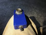
this discussion reminded me to go dig out the test jig I made with the connector from my old dead controller. I am headed out on a road trip this weekend and am going to the Great Western LMTV roundup on our way home next weekend, so needed to get it into our vehicle. It was pretty popular last year helping people find leaks…

I hardwired the H to R pins, so you plug it in and turn on the ignition and it should immediately close the control solenoid. Then you can use the momentary toggle sw positions to supply air or select deflate… i thought about adding a small 5v power supply and a digital voltmeter to show pressure sensor response, and if it is holding a stable pressure. I guess I could also add a LED to indicate wet tank switch state, but haven’t got around to it(too much crap to do:()…

a sealed system should set at tire pressure all day long once pressurized, a leaking system will eventually shift to dump.

IMG_3718.jpeg
 
Last edited:
Lets start with basics.

First - lets assume (I know.... but for the sake of some simple checks) that someone screwed with the wiring to try to hookup to the unit and communicate because A0 trucks don't have coms ports - they are supposed to use a breakout cable that's never around when you need it......

Second - what is your wet tank pressure at compressor unload? If it's not high enough then the CTIS controller will not do anything and eventually fault out with 5 flashing lights and throw a pressure switch code.

Ronmar posits an interesting theory on the multiple maps depending on how you power the unit..... though I would *think* this would show up as options in the Dana Diagnostics software or instructions which it most definitely does not. So I kind of doubt this is a thing - also I've read multiple reports of people simply swapping in controllers from the trucks with higher pressure set points and having them work at the higher pressure which would seem to indicate that the truck wiring is the same on both applications and it's the module programming that's different.
Your comments about tank have me wondering…and it sucks that the TM doesn’t even mention it. I never tested it. I do know the pressure switch test in the TM showed it’s working.

Am I correct to assume there’s a fitting present to hook up a gauge? If not, I suspect folks are just retrofitting something?

Thanks again.

John
 
Last edited:
Top