• Steel Soldiers now has a few new forums, read more about it at: New Munitions Forums!

  • Microsoft MSN, Live, Hotmail, Outlook email users may not be receiving emails. We are working to resolve this issue. Please add support@steelsoldiers.com to your trusted contacts.


cucv glow plug card

mr.travo

Member
422
0
16
Location
Comfort, TX
I the the red wire on top pink/black wire below that, blue wire on the bottom small terminal, then the two orange wires on the bottom.

I pulled my card last night and noticed that it was fried. I called a buddy and got another one but the motor was too warm to cycle the plugs. I am going to try it after work and see if everything is good to go.

I printed out your instructions and will put a meter on it to make sure everything is putting out the correct volts.

I will post up with what I find out.
 

Warthog

Moderator
Super Moderator
Steel Soldiers Supporter
13,775
227
63
Location
OKC, OK
There should be an additional orange wire for a total of three. Two large and one small. It may be laying somewhere. The small orange wire sends a signal back to the controler card to tell it that the plugs are getting power.

Test all the the voltages/resistances before you install the new card.

Here is some interesting reading.

http://www.steelsoldiers.com/cucv/51501-anyone-know-where-these-2-wires-go.html
 

Attachments

Last edited:

Warthog

Moderator
Super Moderator
Steel Soldiers Supporter
13,775
227
63
Location
OKC, OK
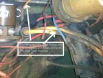
I tested it while it was running and was getting 27v on the main red and 14 or 15 to the pink/black wire. Is this correct?
On a stock system the red wire is hooked to the 24v Postive Terminal Board via the BIG resistor pack on the firewall. So 27v with it running is okay.

The pink/black wire is being fed from the 12v ignition switch. Running it will show 14-15v with the key on. Of course its on...the trucks running...LOL

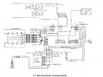
Sounds like everything is wired correctly, now to test the other wires in the circuit before you install the new controller card. It is covered in Paragraph 15, Page 2-62 of the TM 9-2320-289-20.


You will need a ohm/voltmeter and use the chassis ground.

What you will be checking is the:

Purple/white wire #930a - It will show 12v when the key is in the START position. This energizes the controller during starting

Light Blue wire #505 - Jumper this wire to ground with the key in the RUN position. You should hear the relay on the firewall click.

Dark Blue wire #507 - Jumper this wire to ground with the key in the RUN position. You should see the wait light come on. If not, check the bulb

Pink/Black wire #39G - It will show 12v when the key is in the RUN position. This is the power feed for the controller when the key is on. (You have already checked it so it is good)

Orange wire #503a - This is the small orange wire. Jumper the LT BLUE wire to ground with the key in the RUN position. You should hear the relay on the firewall click. And you should also show 24v on the orange wire (It will drop to 12v if all the glowplugs are working correctly)

Yellow wire #151b - This is the wire for the tempature sensor on the block. With the key OFF, check for ~800 ohm with the engine cold. When the engine is hot, the resistance will increase and keep the circuit open, not allowing the controller to turn on the plugs.

Black wire #151a - With the key OFF, you should have 0 ohms. This is the ground for the controller and is connected to the Negative Terminal Block.

Pink/Black and Lt Blue wires at the GP Relay on the firewall - with the key OFF, check the reistance between the two small terminals. You should have 6-10 ohms. Anything highre than that indicates the relay might be bad and needs to be replaced.


After you check all these circuits, you can "safely" install your new controller card without fear of frying it.
 

Attachments

Last edited:

cjtroutt

CW2 26 BDE HHC S6
Steel Soldiers Supporter
756
4
18
Location
C.G. JMTC MICHIGAN
Warthog Thank you for your help my frend could not under stand how to fix his M1028A1 He look over my M1028A2
& still could not get it I had him read this Thread He started to under stand I ran him through the next repair to fix the unit.
bought parts at radio shack fix the Control card test every thing I check his glow plugs & found he replaced them with 12V
insted 24V I pull his truck to my shop with tow bar 4hr later I fix his problem and He learnd how to fix his Truck.

Ps glow plugs are used on alot other types Diesel engines.
Read read read. When help there take it.
Also cummins uses grid heater along timing adv vrv or know as wax adv cold weather 12 valve 5.9l.
again Warthog Thank you again.:beer:
 

Warthog

Moderator
Super Moderator
Steel Soldiers Supporter
13,775
227
63
Location
OKC, OK
Your welcome, glad I could help out.

I try to explain what the Tech Manuals attempt to say in laymans terms. I undestand the manuals, but sometimes they are very vague. At least they are much better than the GM Service Manuals. All they say is "Remove Part", not where it is and what it does....:-?
 

SmokeyDod

New member
206
2
0
Location
Easley, SC
All the cucv veh I know off has 12V glow plugs and NOT 24V. The 24V plugs are used in the humvee trucks whether they had the 6.2 or 6.5 diesels. You can use one of the humvee engines in your cucvs but you have to exchange the glow plugs to the 12V type and also change the solonoid in the inj. pump from the 24V to one from a cucv that all have the 12V. Also there are other things you need to change but just to say all the M1009 & M1008, & other 1028, 1031, 1010 etc have 12v glow plugs.
 

cjtroutt

CW2 26 BDE HHC S6
Steel Soldiers Supporter
756
4
18
Location
C.G. JMTC MICHIGAN
I keep my CUCV MC all times PMCS in number 1 rule around here it can be -30 here cycle Glow Plugs 2 times Power service 911 HEAT FUEL COND to take care junk usdl fuel
it will fire up with no problems. My ford focus did not start from -30 f M1009 is old but I can
count her at any time.
 

2deuce

Well-known member
1,447
110
63
Location
portland, oregon
I was doing a search on the temp sensor and ran across all this good info from warthog. My Question is what tells the GP relay to cycle and then turn off? If its the card, what tells the card to turn off the GP's? Thanks
 

doghead

4 Star General /Moderator
Staff member
Super Moderator
Steel Soldiers Supporter
26,247
1,168
113
Location
NY
There is a temperature sensor on one of the heads. If the engine is "cold", it tells the card to do it's thing. The card measures the GP voltage and engine temp, to know when to shut off(or not come on)


Al look at the GP schematics in the -20 or -34, will give you a good idea of what the card gets and does.
 

2deuce

Well-known member
1,447
110
63
Location
portland, oregon
I'ii take a look at those schematics to try to figure this out. One thing I did was measure the resistance of the temp sensor when cold and there was none. So I thought if I disconnect the sensor I shouldn't get a wait light, that the card would think the engine was hot. Did that, but the wait light came on as usual.
Back to the drawing board.
 

doghead

4 Star General /Moderator
Staff member
Super Moderator
Steel Soldiers Supporter
26,247
1,168
113
Location
NY
Read TM 9-2320-289-20 Troubleshooting, Chapter 2-15. It covers troubleshooting the GP system, step by step.
 

Jake59

Active member
169
97
28
Location
Kaggevinne, Flanders, belgium
Hi Warthog,

Have a question about this line here: " Yellow wire #151b - This is the wire for the temperature sensor on the block. With the key OFF, check for ~800 ohm with the engine cold. When the engine is hot, the resistance will increase and keep the circuit open, not allowing the controller to turn on the plugs."

When I search for this sensor 10045847 and look at the specifications, it seems that they all come with a (sufficiently) high cold resistance which actually decreases as the sensor warms up (e.g. HELLA 6PT 009 107-591: Resistance [Ohm]: 2700, Resistance [Ohm]: 311

I may be mistaken, so please confirm resistance increase with temperature increase.

Thank you,
Jake
 

Jake59

Active member
169
97
28
Location
Kaggevinne, Flanders, belgium
Jake,
Here is the resistance chart of the engine temperature sensor. As the temp increases, the resistance decreases.
Hi AntennaClimber,

Brilliant!!
Thank you.

Immediately ordered a replacement sensor as mine flashes a number for less then half a second when I first connect my Ohm meter, value anywhere from 150 to 900 Ohm and then just reads "1" at all times on the multimeter, which is an open circuit, right?

Last week, I started using the GP Controller Card and the "Wait Light" does come on and go out after a (long) wait, but still less then 1 minute for sure although it does seem quite long.

If this temperature sensor is defect, will it cause the GPs to stay on all the time or does the GP Controller Card nevertheless cut out the GP relay?
I know the "Wait Light" goes out and stays out after the engine has started.

Asking because I had the GP relay coil completely fried last week (this is the 3rd relay already), as well as on the GP Controller Card the 3pin transistor and the last diode which connects to the light blue wire were burnt.

Now I am also worried that the glow plugs may have swollen or be damaged if they stayed fired up way too long...
I guess I'll have to pull a few of them to check... fingers crossed!

GP Controller Card is repaired and I installed a new relay, but I will use only the push button to start with the Controller Card not yet plugged in, until I have the new temperature sensor installed and measured the entire GP wiring harness as per instructions above.

Also found a small black wire (.8 ?) near the firewall on passenger side just hanging around, with an huge round connector at the end. I suspect this to be the ground from GP Controller which hooks up to the 3-bolt Negative Terminal Board?
But I measured resistance between the black wire connector of the GP Temperature Sensor and this round connector and this is an open circuit, which should be a closed loop according to the schematics, right?
Or are there other thin black wires that should hook up to the Neg Term BD ?

Thank you for your help and advice!
Jake
 

antennaclimber

Moderator
Moderator
Steel Soldiers Supporter
1,350
885
113
Location
State College, PA
I doubt that the black wire is part of the GP circuit. You will need to trace it out and see what it is connected to.

Once you get all the new parts installed and the glow plugs tested, let us know how it works.
 

Tinstar

Super Moderator
Super Moderator
Steel Soldiers Supporter
4,256
1,708
113
Location
Edmond, Oklahoma
The glow plugs are inexpensive enough that I would just replace them.
Who knows how long those have been in there.
Most guys use the ACDelco 60Gs

That way you know their all good.
 

Jake59

Active member
169
97
28
Location
Kaggevinne, Flanders, belgium
I doubt that the black wire is part of the GP circuit. You will need to trace it out and see what it is connected to.

Once you get all the new parts installed and the glow plugs tested, let us know how it works.

Hello AntennaClimber,

Tank you for your advice. The black .8 wire indeed has nothing to do with the GP circuit; it goes straight into the diagnostic connector under the dash.

I have ordered a new GP Controller Card from HillBillyWizard but it will only be in my hands by March-April 21; also, I have installed a push-button GP switch to overrun the GP Controller Card, but most of all, I like to learn and understand what, how, why,... and so on... so I prefer to be able to continue using my original GP Controller Card on my M1009 until the new card finally arrives here!

So I hope you can educate me and identify what diode I need to replace the one pointed out on the controller card in the picture below ?

cucv_glow_plug_controller defect.png
As you know, this is the last diode in that part of the PCB and feeds directly into the light blue wire which runs to the GP Relay.
The old diode is completely toasted and unfortunately not identifiable.
What would the correct diode to replace this one?

Thank you,
Jake
 
Top
AdBlock Detected

We get it, advertisements are annoying!

Sure, ad-blocking software does a great job at blocking ads, but it also blocks useful features of our website like our supporting vendors. Their ads help keep Steel Soldiers going. Please consider disabling your ad blockers for the site. Thanks!

I've Disabled AdBlock
No Thanks