• Steel Soldiers now has a few new forums, read more about it at: New Munitions Forums!

  • Microsoft MSN, Live, Hotmail, Outlook email users may not be receiving emails. We are working to resolve this issue. Please add support@steelsoldiers.com to your trusted contacts.

CUCV M1009 electrical issues

MMSINDUSTRIES

New member
13
6
3
Location
Littleton ma
OK and looking back at your photos it looks like from what I can see of one Alternator that the wires all look to be in there. You could just have blown bulbs, fuse, or a bad pcb on the back of the cluster. Also see if any of your fusible links are bulged out or broken. Any of these things can cause issues with the charging system. Speedo is mechanically driven BTW.
I figured that about that speedo. Checked all fusible links. I just recently disconnected, professionally tested, and reinstalled the alternators and it is doing much more than when I first got the vehicle running. The alternators do seem like they are working but maybe intermittently
 

MMSINDUSTRIES

New member
13
6
3
Location
Littleton ma
Cucv fuse box layout.
This is very good thank you
 

GunnyM1009

Well-known member
354
530
93
Location
Roanoke/Alabama
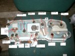
This is a photo of what each socket on the pcb/cluster is for.Cluster 003a (1).jpg
Borrowed from the thread below. It's a good read.
 

MMSINDUSTRIES

New member
13
6
3
Location
Littleton ma
This is a photo of what each socket on the pcb/cluster is for.View attachment 879214
Borrowed from the thread below. It's a good read.
Do you know where I could find picture of diagram for the gen lights mine harness for just that part is missing
 

GunnyM1009

Well-known member
354
530
93
Location
Roanoke/Alabama
Do you know where I could find picture of diagram for the gen lights mine harness for just that part is missing
As I stated the Gen lights are in the same harness that plugs into the back of the instrument cluster. You said your cluster harness was intact. You stated you can not find any cut wires so what leads you to believe your wires for you're Gen lights are missing?
 

MMSINDUSTRIES

New member
13
6
3
Location
Littleton ma
As I stated the Gen lights are in the same harness that plugs into the back of the instrument cluster. You said your cluster harness was intact. You stated you can not find any cut wires so what leads you to believe your wires for you're Gen lights are missing?
I haven’t completely removed the cluster yet but I can see clearly up behind the dash and the gen lights are gone and I can’t tell Any cut wires I’m gonna tear out the cluster when I get a moment
 

GunnyM1009

Well-known member
354
530
93
Location
Roanoke/Alabama
I haven’t completely removed the cluster yet but I can see clearly up behind the dash and the gen lights are gone and I can’t tell Any cut wires I’m gonna tear out the cluster when I get a moment
OK if you look back at the photo posted previously of the back of your instrument cluster. At the bottom right of the photo you will see Gen 1 and Gen 2. These are where the bulb holders go. The signal for them is carried through the printed circuit board from the main plug where all the traces lead just to the left of the Gen 2 socket. There will not be any wires going directly to the Gen lights because the signal comes through the printed circuit board.
 

ezgn

Well-known member
650
1,039
93
Location
Lake Elsinore Ca.
The issue is my gen light sockets and harness are completely missing and I don’t even know where the wires are
OK if you look back at the photo posted previously of the back of your instrument cluster. At the bottom right of the photo you will see Gen 1 and Gen 2. These are where the bulb holders go. The signal for them is carried through the printed circuit board from the main plug where all the traces lead just to the left of the Gen 2 socket. There will not be any wires going directly to the Gen lights because the signal comes through the printed circuit board.
 
Last edited:

MMSINDUSTRIES

New member
13
6
3
Location
Littleton ma
OK if you look back at the photo posted previously of the back of your instrument cluster. At the bottom right of the photo you will see Gen 1 and Gen 2. These are where the bulb holders go. The signal for them is carried through the printed circuit board from the main plug where all the traces lead just to the left of the Gen 2 socket. There will not be any wires going directly to the Gen lights because the signal comes through the printed circuit board.
Oh so your saying it it’s probably just missing the sockets. My mistake I thought they were similar to the glow plug light and water in fuel light and had wired sockets that is very good information thank you
 

GunnyM1009

Well-known member
354
530
93
Location
Roanoke/Alabama
Oh so your saying it it’s probably just missing the sockets. My mistake I thought they were similar to the glow plug light and water in fuel light and bad wired sockets
No the glow plug and water in fuel light are separate from the cluster harness. Everything on that cluster photo gets signal from one large plug. You are welcome. I was new to this at one point as well. Glad I could help.
 

Keith_J

Well-known member
3,657
1,323
113
Location
Schertz TX
Stock alternators are Delco 27SI isolated negative. There are 4 required wires, battery positive, battery negative, excite voltage and voltage sense.
If the excite and sense are wired to the battery positive, the alternator will charge, at reduced output.
Excite and sense are in a two pole plastic plug in the side of the alternator. Battery connections are in the back.
Aside from specialty regulators, this alternator will not function without both excite and sense wires connected and functional.

Excite circuit powers the generator lights with key on engine off. Key switch gives power to the light which then flows to the regulator. If current output of the diode trio is less than the current through the light, the light illuminates. Once the alternator is producing current, there is no flow through the light.

Voltage sense provides for full charge voltage at the battery. The alternator positive will be at a higher voltage than the battery when output current is high. This is because a #6 wire, 4 feet long, has a small resistance to a current of 100 amperes. The current flowing through the sense wire is just a few milliamperes, there is no measurable voltage drop.
 

cucvrus

Well-known member
11,474
10,441
113
Location
Jonestown Pennsylvania
1663236485211.png1663236573040.png Please explain this. No indicators present and the system is charging. This worked on several CUCV's after a slight increase in RPM's for a brief second and normal charge rate at idle. My M1028 had a Gen 2 issue with no indicator Gen 2 light and it would charge normal as soon as I gave the fuel pedal a quick jab. I have since fixed the issue it was a spade connection on the 2 prong white plastic voltage regulator connection. Debating this for educational purposes. Have Great Day.
 

Keith_J

Well-known member
3,657
1,323
113
Location
Schertz TX
View attachment 879358View attachment 879359 Please explain this. No indicators present and the system is charging. This worked on several CUCV's after a slight increase in RPM's for a brief second and normal charge rate at idle. My M1028 had a Gen 2 issue with no indicator Gen 2 light and it would charge normal as soon as I gave the fuel pedal a quick jab. I have since fixed the issue it was a spade connection on the 2 prong white plastic voltage regulator connection. Debating this for educational purposes. Have Great Day.
So the two prong plastic plug on the side of the alternators had a jumper from the voltage sense to the excite wire? That meant the regulator was getting voltage at all times.
Could cause rotor winding to overheat and fail, in addition to discharge of the batteries.
 

cucvrus

Well-known member
11,474
10,441
113
Location
Jonestown Pennsylvania
So the two prong plastic plug on the side of the alternators had a jumper from the voltage sense to the excite wire? That meant the regulator was getting voltage at all times.
Could cause rotor winding to overheat and fail, in addition to discharge of the batteries.
Not the case. I bought this M1009 20+ years ago in stock form 12,674 miles on it and I removed all the interior and parts to rebuild it. I put new batteries in it and started and drove it in and out of my barn over the years and it always glowed and started right up. I would increase the RPM's and the voltmeter would read at the correct charge rate. I left this truck idle many times and used it as a slave start vehicle when I was rebuilding other CUCV's. It always charged batteries and worked like a champ. My M1028 the same thing. It had no Gen 2 light but if I would rev the engine slightly it would go into correct charge rate and stay there until I shut it off. I discovered a broken wire at the voltage regulator and fixed it. I done it on the phone while talking to Antenna Climber. I don't claim to understand the charging system, but I have had several I rebuilt with no cluster in place and always checked the charging system while they were apart.
 

WARWAG

Active member
Before you adjust your shift points do this. Go under the vehicle and look up on the passenger side of the Transmission. You will have a shifting modual on the passenger side of the trans with about a 1" length of rubber hose connecting to the trans. When that hose gets old (80s vehicle) and dried out it can leak. Trust me they do. That will change all of your shift points or make so the trans wont even shift. Weather or not thats the problem replace that hose. I believe its 1?4" but its been years since I had to replace mine. Its was so dry rotted that I thought I had a bad trans. It would take for ever to shift into 2nd gear and at a very high RPM.
 
Top
AdBlock Detected

We get it, advertisements are annoying!

Sure, ad-blocking software does a great job at blocking ads, but it also blocks useful features of our website like our supporting vendors. Their ads help keep Steel Soldiers going. Please consider disabling your ad blockers for the site. Thanks!

I've Disabled AdBlock
No Thanks