• Steel Soldiers now has a few new forums, read more about it at: New Munitions Forums!

  • Microsoft MSN, Live, Hotmail, Outlook email users may not be receiving emails. We are working to resolve this issue. Please add support@steelsoldiers.com to your trusted contacts.

Custom Dash Pod and CTIS controller

ramdough

Well-known member
1,554
1,729
113
Location
Austin, Texas
As many of you know, I cut a brand new dash and added two gauges and 13 switches.

Link to post here…..


This removed the switch pod above the AC evaporator. I also have an Arduino controller from Christian that I wanted to build my own box for.

This is what I came up with…..
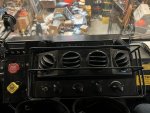
IMG_7951.jpegIMG_7950.jpeg


The silver buttons are the right, left and enter buttons that were on the keypad. They will be only used for setup.

The up and down buttons with be replaced with a single rocker that looks like my dash and I am adding an On/off power switch. These will go on a replacement panel where the old CTIS controller was.

The buttons above the vents are the seat heater controller from the BMW seats.

Sent from my iPhone using Tapatalk
 
Last edited:

ramdough

Well-known member
1,554
1,729
113
Location
Austin, Texas
Anyone know where these attach? The schematic is confusing me on what they tie to. IMG_8087.png

they have two ring terminals. I am assuming they go to ground maybe?
 

GeneralDisorder

Well-known member
Steel Soldiers Supporter
1,998
5,126
113
Location
Portland, OR
A friend 3d printed the housing and I glued it together, sanded, and painted it.


Sent from my iPhone using Tapatalk
Hope it was printed with something like ABS - the heater box gets plenty hot enough to melt many print filaments on it's own. Even at that - ABS starts to get soft around 210 F. A dark colored dash component in direct sunlight can easily approach that. I've had PLA+ printed parts get warped just being in my cab in the summer heat.
 

GeneralDisorder

Well-known member
Steel Soldiers Supporter
1,998
5,126
113
Location
Portland, OR
Thanks! I will have to look for that switch. If it is not there, do I connect them together, tape them off, or ground them?


Sent from my iPhone using Tapatalk
Need the wire numbers to trace them on the schematic. I haven't seen the TL numbers on there. Do you have the CTIS off switch that's part of the arctic kit? The tag seems to suggest it's related. Don't believe I have a switch in that location on my 1079.
 

aw113sgte

Well-known member
Steel Soldiers Supporter
617
909
93
Location
La Crosse, WI
Hope it was printed with something like ABS - the heater box gets plenty hot enough to melt many print filaments on it's own. Even at that - ABS starts to get soft around 210 F. A dark colored dash component in direct sunlight can easily approach that. I've had PLA+ printed parts get warped just being in my cab in the summer heat.
I've had good luck with ASA in "high" temp areas.
 

ramdough

Well-known member
1,554
1,729
113
Location
Austin, Texas
Thanks! I will have to look for that switch. If it is not there, do I connect them together, tape them off, or ground them?


Sent from my iPhone using Tapatalk
I looked ….. I don’t see that switch at all. What should I do with the ends?


Sent from my iPhone using Tapatalk
 

ramdough

Well-known member
1,554
1,729
113
Location
Austin, Texas
Yep need the wire numbers, couldnot find those TL numbers referenced anywhere.
ok, found more. Those go to trailer light switch 190 (S8 )which is for a tractor only.

image001.png

so since I do not have a tractor, my guess is that I should wrap both ends so they do not connect and send a signal anywhere….. thoughts?
 

GeneralDisorder

Well-known member
Steel Soldiers Supporter
1,998
5,126
113
Location
Portland, OR
Correct. Looks like if you connect them it will illuminate the stop lights as if you were activating the Johnny brake for the M1088 trailer. If you ground them you will blow the circuit breaker. So yes heat shrink them individually and label them appropriately. Or follow them back into the harness and delete them entirely if you have no plans to use them in the future.
 

ramdough

Well-known member
1,554
1,729
113
Location
Austin, Texas
Correct. Looks like if you connect them it will illuminate the stop lights as if you were activating the Johnny brake for the M1088 trailer. If you ground them you will blow the circuit breaker. So yes heat shrink them individually and label them appropriately. Or follow them back into the harness and delete them entirely if you have no plans to use them in the future.
Excellent. Thanks!


Sent from my iPhone using Tapatalk
 

ramdough

Well-known member
1,554
1,729
113
Location
Austin, Texas
Ok, just for to be careful, I checked the voltages on the pins and compared that to the manual for the stock controller. The manual lists H and X as power and G, F, and W as grounds.

I get with the engine off:

X to G is 0 V
X to H is -21 V
X to F is 2 V
X to W is -10 V

H to X is 21 V
H to G is 21 V
H to F is 23.7 V
H to W is 16.1 V

Which ones should I use to power the Arduino CTIS and which should be NC?

@Plasa


Sent from my iPhone using Tapatalk
 
Top
AdBlock Detected

We get it, advertisements are annoying!

Sure, ad-blocking software does a great job at blocking ads, but it also blocks useful features of our website like our supporting vendors. Their ads help keep Steel Soldiers going. Please consider disabling your ad blockers for the site. Thanks!

I've Disabled AdBlock
No Thanks