• Steel Soldiers now has a few new forums, read more about it at: New Munitions Forums!

  • Microsoft MSN, Live, Hotmail, Outlook email users may not be receiving emails. We are working to resolve this issue. Please add support@steelsoldiers.com to your trusted contacts.

Custom winch wiring.

Guruman

Not so new member
Steel Soldiers Supporter
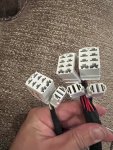
Anyone know where to get a new pin for P913?

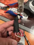
Crimp pulled loose.

View attachment 881285
I read somewhere that someone was able to match the pins to some available from McMaster Carr, although they did not mention which pins were a match. But some careful measuring and digging through the catalog might get you there.

I'd also like to know how the pins get removed from the plug. I have a couple of extraction tools, but none of them seemed to work.
 

Ronmar

Well-known member
3,845
7,474
113
Location
Port angeles wa
Those look similar to molex connectors. On those the male and female pins have barbs that spring outward and rest on a little lip inside their respective hole. They are removed with a piece of tubing with the same inner diameter as the smallest diameter of the hole in the connector. You push in on the wire to lift the barbs off of the shelf while pushing the tube in from the other end to compress the barbs. The molex extractors I have have a center rod which pushes the pin and wire back out of the connector shell once the barbs are compressed.

if you can get the old pin out, you may be able to unfold the crimp and re-crimp it or even solder it onto the wire…
 

ramdough

Well-known member
1,554
1,729
113
Location
Austin, Texas
Ok, been sick, now back at it.


I repaired the pin. Just extracted it, then recrimped. It looked like they did not fully crush it so I just reinserted and crimped it again.

After a bunch of reading, it looks like the A0 harness is just like the A1 harness. So, I think if I just plug it in, the thing should be live.

On the A1, can you fool the engine to let you drive the wheels like the A0 can?

If not, I might swap to the alternate wiring I listed above.

Also, does the k37 relay coil need 12v or 24v? How I “wired” it in my schematic above, I am feeding 24v. I just realized I might have the wrong voltage.

Thanks!


Sent from my iPhone using Tapatalk
 

Ronmar

Well-known member
3,845
7,474
113
Location
Port angeles wa
On an A1 that PTO enable signal from the trans(wire 112) to K37 is 24V.

On an A0 that relay is in the VIM and gets 12V from the TCU along with the Neutral relay as the A0 TCU is fed 12V battery as a power source…
 

ramdough

Well-known member
1,554
1,729
113
Location
Austin, Texas
On an A1 that PTO enable signal from the trans(wire 112) to K37 is 24V.

On an A0 that relay is in the VIM and gets 12V from the TCU along with the Neutral relay as the A0 TCU is fed 12V battery as a power source…
thanks…… maybe you can shed some light on the following.

since I have the A0 accessory harness, and my new dash has 13 additional switches, I am thinking of using the accessory harness for 10 of the switches.

3 will be the default winch/PTO switches.

E6A09C9C-C55D-44F4-9EC3-5B3A37B8AB21.jpeg
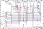
Blue is the accessory harness wires (non-winch/PTO). The truck natively sends 12v direct from the battery to p913-2. I think they changed the wiring from A0 to A1 since A1 split up 1673 into an A and a B wire. On my A0 harness, 1673 is connected to both p905 and p906, so I think I would rather that be on p913-2. Then if I pull out 1674, I can use that as the output of p906. If I pull out 1672, I can use that as the output for p905. On P910 I moved the socket from 3 to 5 to make it consistent with my switches.

Then on this sheet:

F9F84AAE-961A-4D36-8C69-E0A6EB98EEBA.jpeg

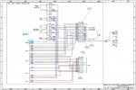
I could pull out the pins in blue and wire those to relays to allow the usage of those switches. On p911 I plan to move socket 3 to 5 to be consistent with my switches.

thoughts?
 
Last edited:

ramdough

Well-known member
1,554
1,729
113
Location
Austin, Texas
thanks…… maybe you can shed some light on the following.

since I have the A0 accessory harness, and my new dash has 13 additional switches, I am thinking of using the accessory harness for 10 of the switches.

3 will be the default winch/PTO switches.

View attachment 882294
Blue is the accessory harness wires (non-winch/PTO). The truck natively sends 12v direct from the battery to p913-2. I think they changed the wiring from A0 to A1 since A1 split up 1673 into an A and a B wire. On my A0 harness, 1673 is connected to both p905 and p906, so I think I would rather that be on p913-2. Then if I pull out 1674, I can use that as the output of p906. If I pull out 1672, I can use that as the output for p905. On P910 I moved the socket from 3 to 5 to make it consistent with my switches.

Then on this sheet:

View attachment 882295

I could pull out the pins in blue and wire those to relays to allow the usage of those switches. On p911 I plan to move socket 3 to 5 to be consistent with my switches.

thoughts?
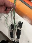
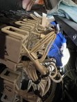
So, I was able to pull the pins from p913…. The ones from p108 and p210 I could not get out. I tried every extractor I could find.

Anyone have any ideas?


Sent from my iPhone using Tapatalk
 

ramdough

Well-known member
1,554
1,729
113
Location
Austin, Texas
Last night I added jumpers to my pulled pins and routed them through the loom. I now have the 10 auxiliary switches wired out to the kick panel end. Then used Tesa tape to clean it up.

7BE08AE6-7078-4ECB-B1AB-A733C5C763A9.jpeg
FA112B50-8BB5-46D3-AAD1-7A69B9FEEB4A.jpeg

I also found an error in my plan. I will update the schematic and repost.

tonight, I plan to splice in the switch light sockets for my 3 additional switches (fuel tank selector is already in the loom, Cruise Control goes straight to the ECM).
 

ramdough

Well-known member
1,554
1,729
113
Location
Austin, Texas
Got the switch lights wired into the accessory harnesses as shown in the schematic above.

134ADB1C-72C6-48F4-BC51-319C46723FC2.jpeg

Only issue I have is that two switches are switching 12v direct battery and the rest are 24v direct battery.

I wanted only one model relay, but at 2350 last night, I stopped looking for the wires labels in the bundle. Probably will have to un-loom it again to find the correct one.
 
Last edited:

Wingnut13

Well-known member
235
562
93
Location
Strafford, NH
Excellent work! It looks great, I sure hope it all works for you on the first flip of a switch. Gotta keep that magic smoke inside all the wires and components……once that stuff gets out, you’re hosed!
 

ramdough

Well-known member
1,554
1,729
113
Location
Austin, Texas
Ok…. Update ….

Weirdness.

My drain switch (upper right) is not working.

Also, all of the new on-off switches only light up when the switch is on. But, my new toggle switch for cruise lights up all of the time. They are all powered off if the same harness. Weird…..

Gonna bundle up the wire ends in tape and stow until I have time to mess with it.


Sent from my iPhone using Tapatalk
 

ramdough

Well-known member
1,554
1,729
113
Location
Austin, Texas
Ok…. Update ….

Weirdness.

My drain switch (upper right) is not working.

Also, all of the new on-off switches only light up when the switch is on. But, my new toggle switch for cruise lights up all of the time. They are all powered off if the same harness. Weird…..

Gonna bundle up the wire ends in tape and stow until I have time to mess with it.


Sent from my iPhone using Tapatalk
I think I figured it out. The switches I bought block the light some when off. In daylight, they are too dim.

So, I must have a disconnect somewhere for the drain switch.


Sent from my iPhone using Tapatalk
 
Top
AdBlock Detected

We get it, advertisements are annoying!

Sure, ad-blocking software does a great job at blocking ads, but it also blocks useful features of our website like our supporting vendors. Their ads help keep Steel Soldiers going. Please consider disabling your ad blockers for the site. Thanks!

I've Disabled AdBlock
No Thanks