• Steel Soldiers now has a few new forums, read more about it at: New Munitions Forums!

  • Microsoft MSN, Live, Hotmail, Outlook email users may not be receiving emails. We are working to resolve this issue. Please add support@steelsoldiers.com to your trusted contacts.

Deep water fording installation?

erasedhammer

Active member
843
60
28
Location
Maryland
I've been reviewing both the parts manual and the installation instructions for the kit, mainly for the vent line installation.
I swear the designers of the kit must have gotten hammered and then drew up the installation instructions. It seems to pay attention to every detail but not the big picture.

Anyone know of a good write up for the kit?
I'm mainly confused with where the new hoses go to and where they connect.

For example:
The kit came with two hoses for the sensor cup to cdr valve but the instructions do not show where the hoses route and why there are two....
 

erasedhammer

Active member
843
60
28
Location
Maryland
And maybe this...
I'm slowly learning how the system operates, I think I understand it now, and it looks like I can just throw it together how ever I want? as long as the hoses end up in the correct places and come from the correct part?

Little confused on what stub the sensor cup plugs into on the cdr valve. That diagram doesn't specifically show and it's not like its labelled on it...lol
 

erasedhammer

Active member
843
60
28
Location
Maryland
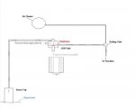
I think you need this. It helped me a lot...
On mine there is a vent line running into the filter on the side of the air cleaner, and then there is also a vent line running into the top of the air cleaner housing. Its not shown on the diagram?
 

Action

Well-known member
3,576
1,558
113
Location
East Tennessee
On mine there is a vent line running into the filter on the side of the air cleaner, and then there is also a vent line running into the top of the air cleaner housing. Its not shown on the diagram?
The rubber hose on the air filter can goes to the air restriction gauge on the dash.

The diagram above shows two lines going to the CDR valve. Doesn't the fording CDR valve only have one small fitting for a hose?
 

fpchief

Well-known member
1,041
220
63
Location
South Alabama
The rubber hose on the air filter can goes to the air restriction gauge on the dash.

The diagram above shows two lines going to the CDR valve. Doesn't the fording CDR valve only have one small fitting for a hose?
Sir, i know this thread has been idle for a while but i noticed you had a question left unanswered. This pic is of my fording CDR. Has two fittings. I will be asking for more assistance on this fording kit soon.


Sent from my SM-G930V using Tapatalk
 

juanprado

Well-known member
Steel Soldiers Supporter
5,614
2,922
113
Location
Metairie/La (N'awlins)
Just installed mine this weekend. The instructions and diagrams have a lot to be desired in my simple mind.

The rubber hose from the deep sensor cup goes to the top crown hose fitting on the cdr valve.

The rubber hose on the bottom of the fording valve goes to the hose connection on the side of the cdr can.

The top plastic line on the fording valve goes straight to the air filter can top fitting closest to the intake stack pipe.

The hard plastic tubing from the middle of the fording valve connects to a t into the power stg cap and then ends at the T where you removed the existing tubing off the air filter can close to the frame and all the other vents that already connect to it.

The bottom of the hydroboost gets a new vent line going down the fender towards the ground that ties into nothing.

The intake stack gets a a vent tube going up and the bottom it connects to the already existing fuel vent filter as there should be a nipple on it that is not being used with a short piece maybe 10 inch of 1/4 hose.

I would recommend buying a new cdr hose and changing it at the same time you install the valve. I don't think it comes in the kit. It is a pain to install the hose and cdr. Mine was a little soft and I would like to have replaced it but did not have one. Hopefully I will not regret that decision down the road....
 
Last edited:

fpchief

Well-known member
1,041
220
63
Location
South Alabama
Just installed mine this weekend. The instructions and diagrams have a lot to be desired in my simple mind.

The rubber hose from the deep sensor cup goes to the top crown hose fitting on the cdr valve.

The rubber hose on the bottom of the fording valve goes to the hose connection on the side of the cdr can.

The top plastic line on the fording valve goes straight to the air filter can top fitting closest to the intake stack pipe.

The hard plastic tubing from the middle of the fording valve connects to a t into the power stg cap and then ends at the T where you removed the existing tubing off the air filter can close to the frame and all the other vents that already connect to it.

The bottom of the hydroboost gets a new vent line going down the fender towards the ground that ties into nothing.

The intake stack gets a a vent tube going up and the bottom it connects to the already existing fuel vent filter as there should be a nipple on it that is not being used with a short piece maybe 10 inch of 1/4 hose.

I would commend buying a new cdr hose and changing it at the same time you install the valve. I don't think it comes in the kit. It is a pain to install the hose and cdr. Mine was a little soft and I would like to have replaced it but did not have one. Hopefully I will not regret that decision down the road....
Sounds about right. I got mine all put on the other day. For the sensor cup, it went to the fitting on CDR valve that is on the same side as the cup correct?

Sent from my SM-G930V using Tapatalk
 

juanprado

Well-known member
Steel Soldiers Supporter
5,614
2,922
113
Location
Metairie/La (N'awlins)
Sounds about right. I got mine all put on the other day. For the sensor cup, it went to the fitting on CDR valve that is on the same side as the cup correct?

Sent from my SM-G930V using Tapatalk

Yes, I call it the top "crown" because that nipple was on a small raised extension at the top facing the A pillar and sensor cup.

All I have left is the dipsticks but the rain caught me.... Occupational hazard here in the moist Banana Republic :)
 

fpchief

Well-known member
1,041
220
63
Location
South Alabama
The oil dipstick requires removing one manifold bolt. I sprayed mine down two days early with PB Blaster and it wast still a #%÷*& it is an allen head also.

Sent from my SM-G930V using Tapatalk
 

juanprado

Well-known member
Steel Soldiers Supporter
5,614
2,922
113
Location
Metairie/La (N'awlins)
The oil dipstick requires removing one manifold bolt. I sprayed mine down two days early with PB Blaster and it wast still a #%÷*& it is an allen head also.

Sent from my SM-G930V using Tapatalk
I saw that bolt but did not realize it was allen. I will soak that puppy now as I won't get to it till sat or sun. Thanks for the tip!
 

Wire Fox

Well-known member
1,252
161
63
Location
Indianapolis, Indiana
The bottom of the hydroboost gets a new vent line going down the fender towards the ground that ties into nothing.

I would recommend buying a new cdr hose and changing it at the same time you install the valve. I don't think it comes in the kit. It is a pain to install the hose and cdr. Mine was a little soft and I would like to have replaced it but did not have one. Hopefully I will not regret that decision down the road....
That sounds risky. I haven't looked this up to verify it myself, but having a below-water vent line opening sounds like this is a recipe for disaster...are you positive that it doesn't T into another line?

Also I had my CDR off when I replaced several gaskets on the top of my engine and made the decision to replace that little hose. Mine was super spongy and filthy inside, yet the actually air intake manifold was very clean.

The oil dipstick requires removing one manifold bolt. I sprayed mine down two days early with PB Blaster and it wast still a #%÷*& it is an allen head also.

Sent from my SM-G930V using Tapatalk
Thank you for that info...I was going to be replacing my oil dipstick prior to the rest of the water fording kit (already have the right transmission dipstick installed) and didn't realize that it was going to be a stubborn bolt. I'll be sure to spray that down next time I'm out there so that it's a little freer when I'm ready to switch it.
 

fpchief

Well-known member
1,041
220
63
Location
South Alabama
That sounds risky. I haven't looked this up to verify it myself, but having a below-water vent line opening sounds like this is a recipe for disaster...are you positive that it doesn't T into another line?

Also I had my CDR off when I replaced several gaskets on the top of my engine and made the decision to replace that little hose. Mine was super spongy and filthy inside, yet the actually air intake manifold was very clean.


Thank you for that info...I was going to be replacing my oil dipstick prior to the rest of the water fording kit (already have the right transmission dipstick installed) and didn't realize that it was going to be a stubborn bolt. I'll be sure to spray that down next time I'm out there so that it's a little freer when I'm ready to switch it.
Yep, it absolutely goes from the hydroboost down the body and terminates open. The small hole on the bottom of hydro boost is open already. This just puts that already open hole farther down. I dont understand why.


Sent from my SM-G930V using Tapatalk
 

Wire Fox

Well-known member
1,252
161
63
Location
Indianapolis, Indiana

fpchief

Well-known member
1,041
220
63
Location
South Alabama

ryanruck

Active member
427
46
28
Location
Cincinnati, OH
I wonder if that is only an outie..meaning that there is a small valve or something that only allows some excess pressure out and nothing can come in. It is a stretch and still doesnt really make sense.

Sent from my SM-G930V using Tapatalk
That would make sense if it acted in a similar manner to the sensor cup where the water coming up into it runs into air in the tube and creates a slight pressure inside it.
 

gcbennet

Member
221
7
18
Location
Trenton, ON
The way I see it, some fancy engineers making six-digits a year designed this stuff to work a certain way and I'm sure there's thousands of Marines out there who can corroborate that it does. Otherwise, there'd be lots of pics all over the net of swamped Humvees on the landing beaches. However, like you guys I would certainly be way happier and more comfortable understanding exactly how the system works on my truck.
 

juanprado

Well-known member
Steel Soldiers Supporter
5,614
2,922
113
Location
Metairie/La (N'awlins)
That sounds risky. I haven't looked this up to verify it myself, but having a below-water vent line opening sounds like this is a recipe for disaster...are you positive that it doesn't T into another line?

Also I had my CDR off when I replaced several gaskets on the top of my engine and made the decision to replace that little hose. Mine was super spongy and filthy inside, yet the actually air intake manifold was very clean.


Thank you for that info...I was going to be replacing my oil dipstick prior to the rest of the water fording kit (already have the right transmission dipstick installed) and didn't realize that it was going to be a stubborn bolt. I'll be sure to spray that down next time I'm out there so that it's a little freer when I'm ready to switch it.
The hydro boost I suspect gets pressure from the power steering as it is pressurized.

I don't think the cdr hose is made of the right material. It feels like a water hose. In my parts selling days, hose for oil applications is multi layered and fiber reinforced. The rubber is usually thicker and has a different texture if that makes any sense. But I am not an engineer and frequent holiday Inn Express...
 
Top