• Steel Soldiers now has a few new forums, read more about it at: New Munitions Forums!

  • Microsoft MSN, Live, Hotmail, Outlook email users may not be receiving emails. We are working to resolve this issue. Please add support@steelsoldiers.com to your trusted contacts.

designing & building custom winch mounts - front & rear

jesusgatos

Active member
2,689
28
38
Location
on the road - in CA right now
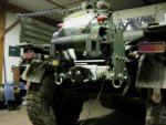
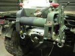
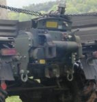
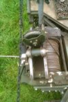
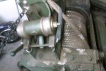
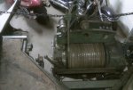
Just found mudguppy's thread about converting an A2 winch to hydraulic power. Lots of good information in there, and a lot of pictures too. Looks like that might be another thing to consider, fitment-wise. At least if I want to direct-mount the pump (instead of using a modified PTO driveshaft and remote-mounting the pump). Looks like things might get pretty tight down there right around the radiator and radiator mounting crossmember.

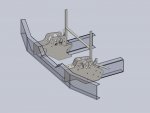
The other big problem is the bumper reinforcing brackets. If I pull the front bumper in any closer to the frame, there's not much room left to zig-zag the frame up/forward. Think I could probably tweak the design to the point where it would be strong enough, but that, coupled with the potential hydraulic motor clearance issues have me thinking that I'm just going to mimic the stock winch mounting geometry this first time around.

Am going to end up building a custom front bumper eventually, but that's lower down on my priority list, and don't want to waste a bunch of time on stuff like that when I've already got my hands full. So will probably revisit this somewhere down the line, and make a new set of winch mounts whenever I get around to making a new front bumper. Will have a much better idea of what I'm working with then anyway.
 

spicergear

New member
2,307
26
0
Location
Millerstown, PA
I would suggest trying to find a blown up 20K Garwood and steel the tensioner set up and bridge off of that. If you're customizing the bumper then you'll prolly set up the roller(s) in that. Keep in mind the bridge is big, and the trolley is a LOT heavier than one might expect. I would guess it's 50lbs and there isn't a hollow area on it! May save you a ton of fab and re-engineering to use those couple of parts. May need to redrill the mouting holes in the bridge to fit the 10K...but no big deal there. Oh, and you'll need to make sure to set up trolley stops to fit the travel you need.
 

jesusgatos

Active member
2,689
28
38
Location
on the road - in CA right now
Thanks, I was going ask about trying to adapt some of that stuff from another application. Would love to see some pics to get a better idea of what you're talking about. All this big truck stuff is new to me.
 

spicergear

New member
2,307
26
0
Location
Millerstown, PA
Some pics of the rear 20K Garwood w/LW on the Mog. I have a video of it dragging my John Deere but it's not up or downloaded. One other thing when designing your system, the large horizontal roller MUST pay the cable directly up into the tensioner pulleys. They're not designed for a forward or rearward load, only side to side or straight up into. You must keep that in mind when designing your roller(s) for that part of the system.
 

Attachments

jesusgatos

Active member
2,689
28
38
Location
on the road - in CA right now
Oh wow! That's no joke! You don't think that weighs much more than 50lbs? So are you saying that I couldn't re-orient a setup like that to lay flat? Wouldn't fit in the rear any way you slice it, just curious.
 

spicergear

New member
2,307
26
0
Location
Millerstown, PA
Ha! In picture 5 of 6, the round trolley stop is 1" aluminum stock...so base your sizes off of that. The trolley is heavy.

I think technically you could actually lay it down however, the trolly would have to captured at its rollers. You would also have to have a center point, like a double roller fairlead window just below the rear crossmember to have the cable come in from the rear there, then have the cable go directly into the tensioner then feed in-line further forward to the upper pulley on the trolley, THEN back rearward into the spool. That is about the only way you could still use the level wind.

Okay, so given that; If you mount the rear winch as far forward as possible, you drastically cut down the angle of the cable going onto the drum. Again if you had a double roller fairlead at the rear crossmember and the winch up the truck six or eight feet it *should* be enough that the cable will spool nicely regardless of the lack of level wind. On Velvet, I had a 10K Garwood mounted under the rear driven by a PTO off the NP205. I had a lifting ring that I would hook into the pintle hook as a fairlead or cable guide. The couple times I used it I had no problem with that winch spooling very nicely back and fourth.

Follow all that?
 

spicergear

New member
2,307
26
0
Location
Millerstown, PA
Oh, also keep in mind that the spool isn't centered on these winches so if you center mount the rear fairlead, you'll have more cable angle at one side of the incoming wrap than the other...if that makes sense.
 

jesusgatos

Active member
2,689
28
38
Location
on the road - in CA right now
Thanks for all the info, and the pics, spicergear. There's way too much going on there though. If anything, might make a simple tensioner. Still working on the front winch mount. Decided to incorporate the lower grill mounts, so I was able to gusset-up the side-plates a bit more. The only thing is, the stock grill mounting tabs on my truck are pretty badly bent, so I can't get any accurate dimensions from them. Can anybody help me out? Gringel-Gringel-Gringel...
 

Attachments

spicergear

New member
2,307
26
0
Location
Millerstown, PA
Nice CAD work, btw! I'm designing something for work using 4 Rockwell front spindle and hubs with custom 12" wheels and solid tires. Every now and then work isn't much work. :mrgreen:
 

jesusgatos

Active member
2,689
28
38
Location
on the road - in CA right now
Oh, thanks, but the devil is in the details. These are still just conceptual models. Once I've figured out all the geometry, I'll have to go back and make all the pieces fit together. That's one really nice thing about designing sheetmetal parts to be laser/water/plasma-cut. Little bit extra time in front of the computer saves a lot of fabrication time. These should go together like a 3D puzzle, kind of like the hubsteps.
 

jesusgatos

Active member
2,689
28
38
Location
on the road - in CA right now
Yeah, I remember seeing that when he posted those pics a while ago. Cool setup, but I want to build something a little burlier. Definitely want to have some kind of continuous front bumper spanning the framerails. Have a pretty good idea of what I want to build, but am going to save that project for later. For now, I'm just going to make these winch/bumper mounts that will put the winch in the stock location and reuse the stock bumper. Will come back to this after mah deuce is all back together. Until then, there are a whole bunch of other things that are a lot more important to get done. Probably not even going to bother with the rear winch mount right now.
 

runk

Active member
542
65
28
Location
Houston, TX
Another marginal power point drawing...:oops:

I'm glad you decided not to move the bumper yet, the more I looked at it while doing yard work all weekend, the more I thought it wouldn't be worth it without a completely new integrated bumper / winch mount / guide assembly. I even then, why bother for the couple of inches ?

I am going to try and modify the grill mounts to move the grill forward about an inch, so I have room to mount my air conditioning condenser between it and the radiator. I may be able to just swap them side to side, with a little tweeking of the grill to get the clearance I need. (And add a lip on the top of the grill to support the hood.)
 

Attachments

jesusgatos

Active member
2,689
28
38
Location
on the road - in CA right now
Wow, your brackets are way different than mine! The slot on mine comes all the way down to somewhere around 2" and they're only about 3" tall. Glad I asked, as one of the reasons I decided to stick with the stock geometry is so that I can make a few extra sets of these winch mounts and figured that everybody else would prefer to maintain the stock geometry. Will build a custom setup for my rig later, and agree with you completely, that it's not worth the trouble unless you go all-out. Would be a lot simpler if I didn't need to retain those shackle mounting points, but I need to keep them so I can use my towbar A-frame hoist. Anyway, plenty of time to think about all that...
 

jesusgatos

Active member
2,689
28
38
Location
on the road - in CA right now
Awwwwwww... :(
Only a matter of priorities. Excited to get this thing all back together and a rear-mounted winch just isn't as important as things like the plumbing and electrical systems when I think about what I'm going to appreciate more on a day-to-day basis living in this thing full-time. Already have the winch, have reserved the space for it, and will get around to it one of these days.
 

Vintage iron

Active member
1,123
15
38
Location
Falmouth Ma.
I have some stock 20,000 lb 5 ton winch mounts, tensioner and a level winder I would sell. Not sure if you still need that stuff. I maybe able to get you the rollers of the winch too. I will know later this week. PM me if I can help you out!
 

jesusgatos

Active member
2,689
28
38
Location
on the road - in CA right now
Another marginal power point drawing...
Whatever works. That's perfect. Only thing I didn't see is the width of the slot, and am assuming it's the same as my brackets (somewhere between .515 and .525"). Another discrepancy seems to be with respect to where the slot is located (front-to-back), relative to the center of the back mounting hole. On my brackets, it looks like the center of that slot is right around .375" forward of the center of that hole, and but yours are more like .3125? hmmm, would sure like to compare measurements from another set of brackets.

I am going to try and modify the grill mounts to move the grill forward about an inch, so I have room to mount my air conditioning condenser between it and the radiator. I may be able to just swap them side to side, with a little tweeking of the grill to get the clearance I need. (And add a lip on the top of the grill to support the hood.)
Planning on doing the exact same thing. Have a huge condensor mounted on the roof rack over the cab, but would like to put an intercooler in front of the radiator. Have an A3 hood that is longer/wider than the A2 hoods, and am not sure whether I'll cut the hood down to the A2 length and make the bulge in the grill, or leave the A3 hood long. Haven't been able to mock anything up yet, so don't really have any idea what might work best.
 
Top
AdBlock Detected

We get it, advertisements are annoying!

Sure, ad-blocking software does a great job at blocking ads, but it also blocks useful features of our website like our supporting vendors. Their ads help keep Steel Soldiers going. Please consider disabling your ad blockers for the site. Thanks!

I've Disabled AdBlock
No Thanks