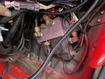
S is the air supply line in from the wet tank.
D is the deflate port you will see a little pressure relief valve in that port.
C connects down to the dump/quick release valves and wheel plumbing.
The control solenoid vents the manifold into that bottom plastic cover. The line connected to that cover just connects to a floor vent port to send the air outside the cab.
The small device with the electrical connector is the pressure sensor.
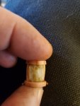
The other connector does connect to the 3 solenoid valves under the cover and its pinout is in the schematic found near the back of each tech manual. I find it easier to control the valves manually using the CTIS controller connector and a pair of jumpers as there is 24v in that connector already(see attached pic).
In the controller connector H is 24v When the main switch is on. Pin R feeds the control solenoid, B feeds the Supply solenoid and C feeds the deflate solenoid. Start the truck, fill the air tanks and shutdown. I take 2 jumper wires and twist one end of each together into a “V” Put the point of the V jumper wire in H. Turn on the main switch and Put the other end of one wire into R. You should hear the control solenoid close. Take the other jumper and briefly(1 second) place it into B. Y0u will hear the supply solenoid open and air flow. This will open all the wheel valves and the system should set at tire pressure as long as the H to R jumper supplies power to the control solenoid. Now leaks are easilly located without the engine running... with a full wet tank, you can do this at least 4 times before you have to recharge the airtanks...
Wheel valves: the tire line is connected to the tiny center port. The truck side line feeds the whole rest of the face of the diaphragm. On the other side of the diaphragm is a spring and atmospheric pressure. High tire air pressure on that center port cant make enough force to lift the diaphragm so the tire port stays closed. When you put only about 6 PSI on the truck side port it can push on the entire diaphragm face and pushes it open easilly, so any more than 6PSI on the truck side = open wheel valve.
Dump Valves: they are a remote pressure regulator. Whatever pressure you apply to the inlet, they try and maintain on the outlet, either by feeding air from inlet to outlet, or by feeding air back to inlet or dumping air from the outlet side to the vent till the outlet matches the inlet. Same type of valve is used on the brakes. Step on the pedal, air flows and brakes are applied, release the pedal and you hear air vented under the truck to quickly release the brake pressure at the wheels.
When you briefly apply air from supply(and the control/vent is closed) that pressure is copied by the dump valves and applied to the wheel valves. Over 6PSI the wheel valves open and everything stabilizes at the average wheel pressure. Or if you continue to supply air, it flows thru the dump valves and thru the wheel valves to flow into the tires...
Remember that little brass relief valve in the D port on the PCU? When you open the deflate solenoid, it connects the manifold to that port and that relief dumps everything above 6.5 PSI(acts like a regulator). That 6.5 PSI left in the manifold is then mimicked by the dump valves and applied to the wheels. Since it is more than 6PSI, the wheel valves stay open, but the tire pressure is far greater, so air flows out of the tires trying to fill that lower pressure line, but the dump valves have 6.5PSI on their input side so will dump any excess air provided by the tires to the vent, to match the 6.5 PSI on their inlet...
Removing the H-R jumper(or shutting off the main switch), opens the control solenoid and vents the PCU manifold to 0PSI. The dump valves copy this on their outlet side, and the wheel valves going below 6PSI close the tire ports...
View attachment 820383


") you can unscrew the vent nipple off of a vented gladhand cover. It is national pipe thread port on the cover and can easily adapt it to a standard air hose fitting then replace the cover on the gladhand.
you can unscrew the vent nipple off of a vented gladhand cover. It is national pipe thread port on the cover and can easily adapt it to a standard air hose fitting then replace the cover on the gladhand.