• Steel Soldiers now has a few new forums, read more about it at: New Munitions Forums!

  • Microsoft MSN, Live, Hotmail, Outlook email users may not be receiving emails. We are working to resolve this issue. Please add support@steelsoldiers.com to your trusted contacts.

Diagnosing CTIS M1078

Lugnuts

Active member
Steel Soldiers Supporter
324
239
43
Location
Myakka City, FL
You have followed the plumbing, left is “T” d to right and front is “T”d to rear. There is no way to send air to just one tire. In emergency mode, the timed routine is changed and the controller simply checks the tire pressure much more frequently and adds as necessary, instead of the normal 15 minute checks. It probably also overrides or loosens the parameters on the need for stable pressure at it’s pressure checks. One leaking tire will deflate on it’s own but as soon as the system is pressurized and all the wheel valves are open, 3 good tires will attempt to fill and equalize the leaking tire...

the quick release/dump valves don’t make much noise when air is applied to their supply. The only time they really make noise is when pressure is released from the supply side and they dump their output side to the vent to equal that low supply pressure. So every time the PCU opens the control solenoid and releases system pressure, they honk briefly.

Now if your supply was feeding slow, as in the issue you described with the protection valve on the wet tank, as the system sent enough pressure thru the dump valves to open the wheel valves, the greater wheel pressure would flow back to the dump valves and be vented until the supply side of the dump built enough pressure to equal the tire pressure...

On my truck, right after that protection valve on the wet tank, there is a T fitting. The smaller line(circled in first pic) runs to the hydraulic manifold to supply air to the cab air suspension valve. The larger line runs directly to the passenger cab floor to feed CTIS and the fan control solenoid... The CTIS line is just out of sight behind it... you can just see the big line to ctis all the way to the right in the second picture...


View attachment 821880View attachment 821881
Thank you. When I get back to it and reseal that hub I will continue on the quest. Until a later date.
Lugnuts
 

Lugnuts

Active member
Steel Soldiers Supporter
324
239
43
Location
Myakka City, FL
I got back to the issue of the leak on front left hub. I procedurally disassembled the tire, drum, removed the planetarium, and pulled the hub. No big deal except one. I have not read the manual but I need to and that is in regard to pulling the rear seal. Seems as if the spindle is larger than the seal and won't come off by pulling but like I say haven't read the manual and any other type of removal doesn't seem logical.
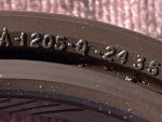
The seals are not the quad rings I expected as in the CTIS M35 so I am asking where is a good vendor to get the seals? Fleetpride says the seal number is good and available for $55 thereabouts but no listing in the company which would mean that they probably really don't want to fool with it. Have I got any advice or vendors from the Comrades of Steel Soldiers. The seal number is Meritor A-1205-Q-2435
The seals look good but it seems perhaps trash and oil in the air line found its way to the hub and perhaps caused an irregular sealing surface. Whatever, replace while I'm there.
And if anyone has experience on that rear seal and would like to respond, please, do so and thanks
Lugnuts

After I wrote this I called Memphis Equipment (Melanie Carter) and they had 5000 of these seals at $33 a piece/ They can ship those out for $10 but ask for the lesser price FedEx in the bag shipping to get that.
 

Attachments

Last edited:

M1078MAN

Well-known member
Steel Soldiers Supporter
673
894
93
Location
SW Va, Roanoke County
You know whats wierd, when I saw that picture of the P# of the seal, it was like flashback..there was a pierod of time we could not get these seals,, we had 15 or so trucks parked for a few months.

Not sure why it flashed back..anyways
 

MrMikey4026

Well-known member
281
417
63
Location
Eatonville Washington
I bought a stack of 10 of those seals on ebay, seems they were like 167$ no freight.
That is like 16,70 each.
Front and rear wheels are the same number.
I bought CTIS and front axle shaft seals the same way, same price.
I don't want to be stranded somewhere with parts several days away.
 

Lugnuts

Active member
Steel Soldiers Supporter
324
239
43
Location
Myakka City, FL
Well, I changed out my seals on Left Front Hub, reinstalled, tested, found a crack in the metal line from hub to Hollow Lug Stud, brazed repaired, and tested again. System held air.
Reassembled for Test Ride. CTIS acted differently. The barking of the Quick Release Valves definitely diminished.
Now the Highway Light kept blinking as the unit worked. As I understand the blinking light means that is is working. When the air stabilizes ie tires are filled to level desired the light goes steady? That is how I understand from what Ronmar wrote earlier it is suppose to work.
About 2 miles into the ride I had 2 blinking lights on the Controller, (extreme ends from each other) One was the Highway Button and one was the Run Button.
I could not find in the manual a description for 2 flashing lights but mention was made of 2 solid lights, Any Feedback?

This is going to be one of those stupid questions (or observation) but I tend to tread where only fools go just for grins and giggles but... if I have a Wet Tank Side leak (one that kicks the Air Compressor on quite frequently but yet I hear the drier vent so I know it is coming to pressure) will it effect the stabaliztion diagnostics on the output side? I realize that if the pressure drops below the Air Pressure Sensor for the Controller that it will cause the unit to turn on and off... will this cause a code to set?
Thank you guys,
Lugnuts
 

MrMikey4026

Well-known member
281
417
63
Location
Eatonville Washington
When I was repairing my CTIS, I had several controllers. Some of them had some very strange errors. I found a good one and it has worked flawlessly.
It might be a good idea to borrow a known working controller, so you don't end up chasing crazy controller issues.
I unplug my controller when ever I disconnect the batteries or jumpstart.
It's always a good idea to disconnect the batteries when welding on the truck.
 

Ronmar

Well-known member
3,848
7,480
113
Location
Port angeles wa
The manual does talk about 2 solid lights not flashing. Maybe yours is not flashing. As MR mikey mentioned the controllers can fail in weird ways. But it would be good to make sure you are delivering all the pre-requisite conditions.

You say the air dryer purges, that means the governor has met its set pressure. But at what pressure is it set? You need to connect a pressure gauge to the wet tank to confirm that It reliably goes above the 117 psi CTIS switch point. (Governor should be set to 125 PSI).

If you look at the possible causes for the 2 light fault, governor adjustment and air supply from wet tank to ctis are right up there at the top of the list. That air supply includes the protection valve. It looks like a regulator on the back side of the wet tank, but it acts like a CTIS wheel valve and only allows air greater than 85 PSI to exit the wet tank, thus retaining at least 85 PSI to feed the brake system. If it is not flowing properly that could be interfering with the process...

from your description it sounds as if it is starting out normal, single light flashing as it is working. But eventually it fails to meet some goal, like not filing fast enough, and the display changes to 2 lights... if you are not reliably exceeding/closing that117 PSI Pressure switch or have too much air leaking away instead of feeding the tires that could also be your issue.
 

tennmogger

Well-known member
Steel Soldiers Supporter
1,579
543
113
Location
Greenback, TN
I have an LMTV 1078 that times out with two lights as yours does. It is a timeout at about 15 minutes if the system is not able to achieve the pressure goal. In my case the failure is because of a leaky seal in the left front axle/hub. I can hear a whistle from it sometimes. I have found that moving the wheel about half a revolution will allow the completion of the cycle. Of course I need to fix that seal. Summary, a leak anywhere that is slow enough to not immediately fault the system but bad enough that high pressure leaks out, will cause that fault. My system achieves XC exery time. Pushing the HWY switch again makes the system start over.
 

JD4044M

Well-known member
465
999
93
Location
Okanogan, WA. 98840
OK My CTIS is working now and reading this thread it is not mentioned what pressures are for the tires? My CTIS will set the tires at HWY 58 PSI and at the Sand 32 PSI haven't checked the XC PSI yet. So is this right on the pre set? They sure do go down fast compared to filling back up!
 

Awesomeness

Well-known member
Steel Soldiers Supporter
1,813
1,519
113
Location
Orlando, FL
OK My CTIS is working now and reading this thread it is not mentioned what pressures are for the tires? My CTIS will set the tires at HWY 58 PSI and at the Sand 32 PSI haven't checked the XC PSI yet. So is this right on the pre set? They sure do go down fast compared to filling back up!
The TM has a chart of what pressure each button corresponds to (and what speed you can drive at with it).
 

Celticlady

Active member
131
127
43
Location
Arkansas
Yes, I have downloaded the Tech Manual and thank you for sharing that. My question and I haven't found it in the site is that pertaining to Software for Computer diagnostics of the system. Is it obtainable? And where might it be located? And has any person on this site done it and know it? I have 5 blinking lights and that lists a great amount of codes. Not insurmountable but perhaps looking to be more specific.
Your assistance would be greatly appreciated!!
Lugnuts

Lugnuts, Follow what Ron says to do. He also has a process to jumper the controller plug to find the leak.

IT WORKS. It does take 2 people

Had my huge leak found and repaired in day using what he said to do.
 

JD4044M

Well-known member
465
999
93
Location
Okanogan, WA. 98840
The TM has a chart of what pressure each button corresponds to (and what speed you can drive at with it).
Boy I down loaded lots of good TM information on this system!! I know a lot more on how it works except the chart on pressures? I really looked too even search this site. I still have to find the Neg Ground that feeds the dash to the frame. I think it is messing with the control box working off and on before? Seems like the truck needed drove for a while to loosen it up and also make it run nicer, shift better ect. Got most of the little bugs solved I feel OK on long drives now. One good part 100s of miles driven and no oil/fluid leaks found on the drivetrain!!
 
Last edited:

Mullaney

Well-known member
Steel Soldiers Supporter
Supporting Vendor
7,716
19,766
113
Location
Charlotte NC
OK My CTIS is working now and reading this thread it is not mentioned what pressures are for the tires? My CTIS will set the tires at HWY 58 PSI and at the Sand 32 PSI haven't checked the XC PSI yet. So is this right on the pre set? They sure do go down fast compared to filling back up!
.
CTIS definitely inflates a lot slower than it drains air from the tires.

I personally hadn't given it a lot of thought. Drain, get out of the muck or sand, possibly in a hurry. Then hit the inflate button while moving slowly away from the problem area (or people).

My guess is that depending on how low the tire pressure - CTIS would suspend filling tires to keep the pressure above 90psi (Corrected to 85psi) and keep the truck still moving forward. There is definitely a regulator valve on the tank that feeds CTIS.
 
Last edited:

Third From Texas

Well-known member
2,766
6,498
113
Location
Corpus Christi Texas
Boy I down loaded lots of good TM information on this system!! I know a lot more on how it works except the chart on pressures? I really looked too even search this site. I still have to find the Neg Ground that feeds the dash to the frame. I think it is messing with the control box working off and on before? Seems like the truck needed drove for a while to loosen it up and also make it run nicer, shift better ect. Got most of the little bugs solved I feel OK on long drives now. One good part 100s of miles driven and no oil/fluid leaks found on the drivetrain!!
Those pressures are normal (58 psi HWY, etc). Well, normal for the truck (not really the tires). You should land that ground, but it is redundant.

You can raise those pressures and many here have. Solutions range from $10-a couple hundred.

I went with the simple transducer swap.


But there's a very spiffy Arduino replacement that a fellow on here sells. If your controller ever takes a dump or you want finite control, that's the way to go, IMO!


Ronmar

Well-known member
3,848
7,480
113
Location
Port angeles wa
My guess is that depending on how low the tire pressure - CTIS would suspend filling tires to keep the pressure above 90psi and keep the truck still moving forward. There is definitely a regulator valve on the tank that feeds CTIS.
that regulator looking thing is a protection valve. It works just like the wheel valves except it takes 85PSI on the wet tank side to open and allow air out, so it won’t let CTIS draw the wet tank below 85 PSI. y0u can(and should) confirm this with a gauge connected to the wet tank.

The controller uses the pressure switch on the wet tank to cycle the system on and off to push the wet tank pressure above 117 PSI to recharge the service tanks to at least that pressure… the tires, especially when low will drain the wet tank on my truck down to that 85PSI cutoff in as little as 3 seconds…
 

Awesomeness

Well-known member
Steel Soldiers Supporter
1,813
1,519
113
Location
Orlando, FL
Boy I down loaded lots of good TM information on this system!! I know a lot more on how it works except the chart on pressures? I really looked too even search this site.
I think it's in the -10 Operator's Manual. There are several sections in there that outline what all the buttons in the cab do, and others that describe how to operate different functions of the truck in different environments.

Seems like the truck needed drove for a while to loosen it up and also make it run nicer, shift better ect. Got most of the little bugs solved I feel OK on long drives now. One good part 100s of miles driven and no oil/fluid leaks found on the drivetrain!!
The more you drive these trucks, the better they seem to be. Even if you don't have an actual need to, drive it on some errands each week. It will be much happier.
 

Subby808

New member
5
11
3
Location
Arizona
S is the air supply line in from the wet tank.

D is the deflate port you will see a little pressure relief valve in that port.

C connects down to the dump/quick release valves and wheel plumbing.

The control solenoid vents the manifold into that bottom plastic cover. The line connected to that cover just connects to a floor vent port to send the air outside the cab.

The small device with the electrical connector is the pressure sensor.

The other connector does connect to the 3 solenoid valves under the cover and its pinout is in the schematic found near the back of each tech manual. I find it easier to control the valves manually using the CTIS controller connector and a pair of jumpers as there is 24v in that connector already(see attached pic).

In the controller connector H is 24v When the main switch is on. Pin R feeds the control solenoid, B feeds the Supply solenoid and C feeds the deflate solenoid. Start the truck, fill the air tanks and shutdown. I take 2 jumper wires and twist one end of each together into a “V” Put the point of the V jumper wire in H. Turn on the main switch and Put the other end of one wire into R. You should hear the control solenoid close. Take the other jumper and briefly(1 second) place it into B. Y0u will hear the supply solenoid open and air flow. This will open all the wheel valves and the system should set at tire pressure as long as the H to R jumper supplies power to the control solenoid. Now leaks are easilly located without the engine running... with a full wet tank, you can do this at least 4 times before you have to recharge the airtanks...

Wheel valves: the tire line is connected to the tiny center port. The truck side line feeds the whole rest of the face of the diaphragm. On the other side of the diaphragm is a spring and atmospheric pressure. High tire air pressure on that center port cant make enough force to lift the diaphragm so the tire port stays closed. When you put only about 6 PSI on the truck side port it can push on the entire diaphragm face and pushes it open easilly, so any more than 6PSI on the truck side = open wheel valve.

Dump Valves: they are a remote pressure regulator. Whatever pressure you apply to the inlet, they try and maintain on the outlet, either by feeding air from inlet to outlet, or by feeding air back to inlet or dumping air from the outlet side to the vent till the outlet matches the inlet. Same type of valve is used on the brakes. Step on the pedal, air flows and brakes are applied, release the pedal and you hear air vented under the truck to quickly release the brake pressure at the wheels.

When you briefly apply air from supply(and the control/vent is closed) that pressure is copied by the dump valves and applied to the wheel valves. Over 6PSI the wheel valves open and everything stabilizes at the average wheel pressure. Or if you continue to supply air, it flows thru the dump valves and thru the wheel valves to flow into the tires...

Remember that little brass relief valve in the D port on the PCU? When you open the deflate solenoid, it connects the manifold to that port and that relief dumps everything above 6.5 PSI(acts like a regulator). That 6.5 PSI left in the manifold is then mimicked by the dump valves and applied to the wheels. Since it is more than 6PSI, the wheel valves stay open, but the tire pressure is far greater, so air flows out of the tires trying to fill that lower pressure line, but the dump valves have 6.5PSI on their input side so will dump any excess air provided by the tires to the vent, to match the 6.5 PSI on their inlet...

Removing the H-R jumper(or shutting off the main switch), opens the control solenoid and vents the PCU manifold to 0PSI. The dump valves copy this on their outlet side, and the wheel valves going below 6PSI close the tire ports...


View attachment 820383
Thank you so very much for this write up. I've been pulling my hair out troubleshooting my CTIS system, but believe this writeup will help solve my problem. Else, I'm inclined to do what you did, and make it a manual system.
 

Third From Texas

Well-known member
2,766
6,498
113
Location
Corpus Christi Texas
Thank you so very much for this write up. I've been pulling my hair out troubleshooting my CTIS system, but believe this writeup will help solve my problem. Else, I'm inclined to do what you did, and make it a manual system.
Another option is one made using an Arduino mini-PC kit. There's a member here who makes them and they've gotten some pretty great reviews.

 
Top
AdBlock Detected

We get it, advertisements are annoying!

Sure, ad-blocking software does a great job at blocking ads, but it also blocks useful features of our website like our supporting vendors. Their ads help keep Steel Soldiers going. Please consider disabling your ad blockers for the site. Thanks!

I've Disabled AdBlock
No Thanks