• Steel Soldiers now has a few new forums, read more about it at: New Munitions Forums!

  • Microsoft MSN, Live, Hotmail, Outlook email users may not be receiving emails. We are working to resolve this issue. Please add support@steelsoldiers.com to your trusted contacts.

Does the PPD do more than reverse polarity protect ? Modern replacement for PPD ?

MatthewWBailey

2025 !!
Steel Soldiers Supporter
874
1,594
93
Location
Mesa Colorado
Found all of your 28SI alternator posts here:


Pretty much the exact setup I was searching for. I will be knocking that off completely if/when my 100A Neehoff dies. Hoping to extend its life a bit by running a 24v setup only, but I am getting some voltage spikes on the trans currently as I mentioned in first post...

I tried searching your posts but didn't see any reference, what year/make is your truck ? A1 or A1R ?
'04 A1. I also had a few over voltage codes on the trans. It All began when the starter shorted. I still have to take the pulled Neihoff to the repair shop.

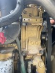
if you do this swap double check the existing belt length before ordering a shorter one. I used the wrong length at first. So my initial replacement was barely able to fit.
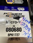
EF06A159-80A2-41DB-B6A9-BF68D251D41C.jpeg
 
Last edited:

Aviator4x4

Active member
Steel Soldiers Supporter
133
248
43
Location
NC
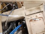
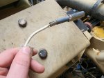
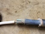
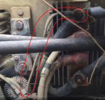
WTF is this ? Is this normal ? I tried searching the forums and using google with "site:" prefix and not sure what to make of this... It was attached to the top lug of the PPD (fed directly from batts or alt). Is this normal ?


20240504_143811.jpg


20240504_144026.jpg
20240504_144053.jpg

I know what this cable is for (INLET AIR HEATER), but not why it becomes what looks like a 10AWG or 12AWG cable, and then back to 4AWG... Is this some kind of strange "fuse" ? I don't get it. Not sure I've seen anything like it before.


1714939604911.png

I pulled this snip from one of Helicools videos... I also don't have the shunt and no evidence it's ever been installed on my '02 A1
1714940413618.png
 

GeneralDisorder

Well-known member
Steel Soldiers Supporter
2,093
5,340
113
Location
Portland, OR
That's a fusible link. It is designed that way on purpose to burn through if the rated amperage draw of the heater exceeds it's rating. A "fusible link" is simply a section of wire that is intentionally several wire gauges smaller to contain the failure to a specific location. It's just like the various colored fusible links that feed high draw accesories and fuse panels on any old Chevy - you generally see them attached to the lug on the starter solenoid, etc. And yes that is the correct location - it should be on the battery 24v lug on the PPD/LBCD.

A1+ trucks don't have the shunt - they don't have the analog diagnostic plug that it was designed to feed. A1+ diagnostic kits use an inductive clamp rather than an on-board shunt and have only full digital diagnostic ports.
 

MatthewWBailey

2025 !!
Steel Soldiers Supporter
874
1,594
93
Location
Mesa Colorado
WTF is this ? Is this normal ? I tried searching the forums and using google with "site:" prefix and not sure what to make of this... It was attached to the top lug of the PPD (fed directly from batts or alt). Is this normal ?


View attachment 922696


View attachment 922697
View attachment 922698

I know what this cable is for (INLET AIR HEATER), but not why it becomes what looks like a 10AWG or 12AWG cable, and then back to 4AWG... Is this some kind of strange "fuse" ? I don't get it. Not sure I've seen anything like it before.


View attachment 922695

I pulled this snip from one of Helicools videos... I also don't have the shunt and no evidence it's ever been installed on my '02 A1
View attachment 922699
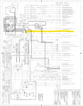
I believe that is the inline fuse F3. My AIH lead has the same transition portion. F3 on the schematic has to be there since that cable only goes from LBCD to AIH.

DC62BD41-5C6D-4551-B7D3-05A455AC0299.jpeg
 

Aviator4x4

Active member
Steel Soldiers Supporter
133
248
43
Location
NC
That's a fusible link. It is designed that way on purpose to burn through if the rated amperage draw of the heater exceeds it's rating. A "fusible link" is simply a section of wire that is intentionally several wire gauges smaller to contain the failure to a specific location. It's just like the various colored fusible links that feed high draw accesories and fuse panels on any old Chevy - you generally see them attached to the lug on the starter solenoid, etc. And yes that is the correct location - it should be on the battery 24v lug on the PPD/LBCD.

A1+ trucks don't have the shunt - they don't have the analog diagnostic plug that it was designed to feed. A1+ diagnostic kits use an inductive clamp rather than an on-board shunt and have only full digital diagnostic ports.
Interesting, thanks for confirming what I thought its purpose was. I guess my question is, why not use a replaceable fuse ? Not a "critical" system and can confine the failure to a fairly open area (near the PPD) ?

I believe that is the inline fuse F3. My AIH lead has the same transition portion. F3 on the schematic has to be there since that cable only goes from LBCD to AIH.

View attachment 922700
Ahh, thanks. I'm an aspiring schematic reader and not quite there yet. This appears to confirm what you say:

1714951405237.png


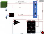
And yeah... as Ronmar says, I have an early A1 truck so it is somewhere between an A0 and an A1. It's a fun challenge haha. Near as I can tell, this is how the truck was wired to/from the PPD. I've made this by looking at the A0 schematics, the A1 schematics, and then looking at my truck to see what is there and what size the cabling is (in case anyone needs/wants to do this in the future, I've also tried to include links to exactly what I'm using component wise).

1714951965473.jpeg

So, I think I'm going to fuse that just like anything else off of the 24V 600A busbar with a 100A MRBF Fuse in a Block Terminal.

1714952086311.jpeg

1892W @ 24V = ~78A
If my voltage drops to 22V, it'll draw 86A.
1714951346766.png

To pass 90-100A across 10' with a voltage drop of 3% or less I need 4AWG (Which it already is, so I'll hydraulic crimp splice it with some Ancor Marine Grade Primary Wire 4AWG from the PPD area to the battery box.
1714951536269.png
 

Aviator4x4

Active member
Steel Soldiers Supporter
133
248
43
Location
NC
Your ohms law is not obeying your command. Wattage is not constant, resistance is. If the full
Load is 1892/24=78.8A, then V/I=R is 24/78.8=0.3044=R. At 22v, V/R=I = 72.3A

only with motors (induction) will current go up when voltage drops.
Thanks, appreciate that correction. Quite familiar with ohms and kirchoffs laws and shouldnt have made such a rookie error ! I mostly deal with micro controllers and stepper motors kind of stuff.

Thems fuses and holders cost good money boy…:)
Haha you're telling me... I feel like a fire would be more costly though. Not sure that's ever happened, but I would be the unlucky one to experience it. Especially with removing the PPD.

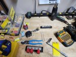
They're pretty common in boat, RV, and offroad builds. Blue Sea makes good stuff. I bought the MRBFs for this but I already have the 285 series and two of the 3 bus bars from previous builds.

1000008581.jpg
 

hike

—realizing each day
Steel Soldiers Supporter
539
851
93
Location
Texas Hill Country
Great thread and work. The photographs are helpful.

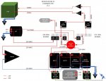
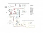
We headed a similar, though different path than you and @MatthewWBailey with ours in this thread. Pulled out the LBCD and remote disconnect relays, swapped in a 24v 200a alternator and mounted a Victron 24v/12v 70a converter to the inside of the passenger footkick connected between X1 (24v batt) X2 (12v batt) on the PDP. Removing the 'center' 12v connection to simplify the battery balancing and charging. We are relying upon the Victrons for all 12v power though very unlikely both will go down at once.


concept-electrical-cab-chassis-1.5-progress-20240310.jpg

Looking forward to watching your build progress. Thank you for sharing—
 

GeneralDisorder

Well-known member
Steel Soldiers Supporter
2,093
5,340
113
Location
Portland, OR
Sometimes you don't want the operators or even the field techs to pop in another fuse or bypass the fuse easily. The AIH is very high current draw and a malfunction down stream from the PPD/LBCD could easily cause a fire. When that link burns through the techs will have to go into the TM and order the whole harness from the PPD/LBCD to the AIH relay - hopefully addressing whatever short may have caused a burnt out link. It's also cost effective and if absolutely necessary can be made in the field with only some scraps of wire. Fuses have to be manufactured in a factory. In the Army we call this "Field Expedient" - in a combat zone that's the civilian equivalent of "If it's stupid but it works - then it's not stupid".

Now of course PVT Snuffy can still really F up. My truck is a good example - that AIH lead at the LBCD was connected to 12v batt and so my AIH caused a huge voltage drop on the 12v side till I found and fixed the mistake. Although to the designers credit this did not damage anything - it just didn't work correctly.
 

coachgeo

Well-known member
5,150
3,466
113
Location
North of Cincy OH
Sometimes you don't want the operators or even the field techs to pop in another fuse or bypass the fuse easily. The AIH is very high current draw and a malfunction down stream from the PPD/LBCD could easily cause a fire. ...

Now of course PVT Snuffy ..
If I had any kids.... PVT snuffy would be one of them... What is an AIH?

Air Inlet Heater?
 

Aviator4x4

Active member
Steel Soldiers Supporter
133
248
43
Location
NC
Great thread and work. The photographs are helpful.

We headed a similar, though different path than you and @MatthewWBailey with ours in this thread. Pulled out the LBCD and remote disconnect relays, swapped in a 24v 200a alternator and mounted a Victron 24v/12v 70a converter to the inside of the passenger footkick connected between X1 (24v batt) X2 (12v batt) on the PDP. Removing the 'center' 12v connection to simplify the battery balancing and charging. We are relying upon the Victrons for all 12v power though very unlikely both will go down at once.


View attachment 923200

Looking forward to watching your build progress. Thank you for sharing—
Oh yes, I am very familiar with your threads ! It is also quite helpful (both your diagrams and the knowledgeable members talking through the "why" behind your couple of revisions).

Did you do an ELA and decide you needed 200A ? That Leece Neville A0014740JB is a really awesome alternator, but also $1k vs the $300 28SI Delco Remy one. Also, do you recall if the stock alternator is a J180 long or short hinge ? I know I can go measure it, just hoping you might remember.

I of course want 200A of 24v, because why not. But I'm not sure I'd need more than the 100A of the 28SI ? If the community could check my math...

My plan is 4x 24M AGM batteries with ~70Ah each in them.

Worst case, a cold start:
Inlet heater @ 86A for 12sec = 0.289Ah
Starter, 7.8kW, 24v, 325A, 30sec = 2.71Ah
--------------
2.995 - Total Ah for starting

With a 100A continuous alternator
Say 20A for cab 24v
30A of 24v for 60A of cab 12v
I'd have 50A from the alternator for recharging, which would be ~3.59mins to recharge ? Does not seem like a lot... my math might be wrong
 

Attachments

MatthewWBailey

2025 !!
Steel Soldiers Supporter
874
1,594
93
Location
Mesa Colorado
Oh yes, I am very familiar with your threads ! It is also quite helpful (both your diagrams and the knowledgeable members talking through the "why" behind your couple of revisions).

Did you do an ELA and decide you needed 200A ? That Leece Neville A0014740JB is a really awesome alternator, but also $1k vs the $300 28SI Delco Remy one. Also, do you recall if the stock alternator is a J180 long or short hinge ? I know I can go measure it, just hoping you might remember.

I of course want 200A of 24v, because why not. But I'm not sure I'd need more than the 100A of the 28SI ? If the community could check my math...

My plan is 4x 24M AGM batteries with ~70Ah each in them.

Worst case, a cold start:
Inlet heater @ 86A for 12sec = 0.289Ah
Starter, 7.8kW, 24v, 325A, 30sec = 2.71Ah
--------------
2.995 - Total Ah for starting

With a 100A continuous alternator
Say 20A for cab 24v
30A of 24v for 60A of cab 12v
I'd have 50A from the alternator for recharging, which would be ~3.59mins to recharge ? Does not seem like a lot... my math might be wrong
Just a tidbit, the AIH will run for 2-5 minutes or longer on a cold start without a rapid warm up. Once cold air gets pulled thru there. My new alt is pulling 105amps for that long if it's <30 outside until the trans heats up.
 

Ronmar

Well-known member
3,901
7,573
113
Location
Port angeles wa
Oh yes, I am very familiar with your threads ! It is also quite helpful (both your diagrams and the knowledgeable members talking through the "why" behind your couple of revisions).

Did you do an ELA and decide you needed 200A ? That Leece Neville A0014740JB is a really awesome alternator, but also $1k vs the $300 28SI Delco Remy one. Also, do you recall if the stock alternator is a J180 long or short hinge ? I know I can go measure it, just hoping you might remember.

I of course want 200A of 24v, because why not. But I'm not sure I'd need more than the 100A of the 28SI ? If the community could check my math...

My plan is 4x 24M AGM batteries with ~70Ah each in them.

Worst case, a cold start:
Inlet heater @ 86A for 12sec = 0.289Ah
Starter, 7.8kW, 24v, 325A, 30sec = 2.71Ah
--------------
2.995 - Total Ah for starting

With a 100A continuous alternator
Say 20A for cab 24v
30A of 24v for 60A of cab 12v
I'd have 50A from the alternator for recharging, which would be ~3.59mins to recharge ? Does not seem like a lot... my math might be wrong
ok, perhaps some of your numbers are off.

1. A starter rarely pulls its full power rating except briefly initially getting things turning, and only a fraction of that thereafter even when cold.
2. Pulling large amounts of current out of a battery throws basic AH calculations out the window due to Mr Pukert and his loss calculations
3. The full power light load of an A0 M1079(lots of incandescent lights) is only 33A… Upper 20’s for a M1078, so ~15A@24V if you are all incandescent. LEDs cut this in half.
4. I think the 20A@24v is a little fat, even with the blower running.
5. The issue with AGMs compared to wet cells is they are looking for 45% of the AH rating when they are thirsty. If you are contemplating 4ea @70AH in a series/parallel(140AH@24), the batteries all by themselves will be looking for nearly 70A. Workable at 100A alt output…

The recharge rate is solely determined by the battery chemistry, providing the alternator has the output capacity to support that draw(45%AH for AGN, 25%AH for wet cells). That is why charging Lithium direct from an alt is an issue as their low internal resistance/high draw rates, can overwhelm and damage an alt… I am sure it will take longer that 4 minutes to recover from a cold start, but it should do it fairly rapidly as the batteries allow…
 
Last edited:

hike

—realizing each day
Steel Soldiers Supporter
539
851
93
Location
Texas Hill Country
Did you do an ELA and decide you needed 200A ? That Leece Neville A0014740JB is a really awesome alternator, but also $1k vs the $300 28SI Delco Remy one. Also, do you recall if the stock alternator is a J180 long or short hinge ? I know I can go measure it, just hoping you might remember.

I of course want 200A of 24v, because why not. But I'm not sure I'd need more than the 100A of the 28SI ? If the community could check my math...
Others are best at the math, though we have decided to mount a rooftop 24v AC unit on the cab which adds a 'new' 70a at max.

[@GeneralDisorder and I have had several conversations upon this and I understand his points well. If we find a complete RedDot Gen2 kitted unit I'd likely purchase it, though spending the time to source all the bits and pieces and installing the separate items, adding another idler to the main shaft just doesn't add up with my skill set and time available right now. Using an electric rooftop unit is not likely the best choice for most folks here.]

Since the cab and chassis need (and CAT specs) only two batteries we are splitting the four into two 2-series banks separated by a Victron Cyrix unit. That way the cab and chassis 2-series bank is maintained 'first' and the added accessory 2-series bank is maintained with the excess the cab and chassis bank does not draw. The Cyrix also allows the second bank to be used at start, if needed. This way we have a 'back up' bank of batteries with us at all times to run the main systems.

Maintaining four batteries with only a 100a alternator is likely fine when the batteries are fresh, though when they are drawn down significant our understanding is they bring us too close to the alternator's limit for the kind of travel we typically do.

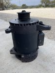
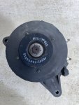
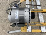
I thought I had photos with a tape measure for the Neihoff, though not finding them. I believe it is a long J180 and the tabs are offset, not 180° from each other.

IMG_4049.jpeg

IMG_4042.jpeg

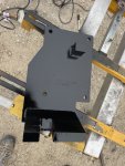
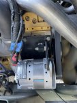
We did need to modify the bracket and add a rigid upper arm. The original length serpentine works without adjusting the tension pulley.

IMG_4001.jpeg

IMG_4003.jpeg

IMG_4015.jpeg

@MatthewWBailey went with a pad mount and I like that idea very much.

IMG_3993.jpeg

Hopefully that helps—
 

mechanicjim

Member
90
40
18
Location
Chicago il
Oh yes, I am very familiar with your threads ! It is also quite helpful (both your diagrams and the knowledgeable members talking through the "why" behind your couple of revisions).

Did you do an ELA and decide you needed 200A ? That Leece Neville A0014740JB is a really awesome alternator, but also $1k vs the $300 28SI Delco Remy one. Also, do you recall if the stock alternator is a J180 long or short hinge ? I know I can go measure it, just hoping you might remember.

I of course want 200A of 24v, because why not. But I'm not sure I'd need more than the 100A of the 28SI ? If the community could check my math...

My plan is 4x 24M AGM batteries with ~70Ah each in them.

Worst case, a cold start:
Inlet heater @ 86A for 12sec = 0.289Ah
Starter, 7.8kW, 24v, 325A, 30sec = 2.71Ah
--------------
2.995 - Total Ah for starting

With a 100A continuous alternator
Say 20A for cab 24v
30A of 24v for 60A of cab 12v
I'd have 50A from the alternator for recharging, which would be ~3.59mins to recharge ? Does not seem like a lot... my math might be wrong
A note on alternator ratings, they are rated via SAE J56 spec, which is 72 degree stabilized temp 6,000 alt shaft speed what it makes goes on the name plate.
so in general on most diesels the alt spins 3 to1 of engine, engine idle say 700 rpm is 2100 alternator shaft speed. so a 100 amp alternator will only make 100 amps at about 2000 engine rpm 6000 alt shaft speed. what you need to look at is the idle output that's where the truck will spend most of its time. Unless you like doing highway speed or fast idling the truck all the time.
 
Top
AdBlock Detected

We get it, advertisements are annoying!

Sure, ad-blocking software does a great job at blocking ads, but it also blocks useful features of our website like our supporting vendors. Their ads help keep Steel Soldiers going. Please consider disabling your ad blockers for the site. Thanks!

I've Disabled AdBlock
No Thanks