• Steel Soldiers now has a few new forums, read more about it at: New Munitions Forums!

  • Microsoft MSN, Live, Hotmail, Outlook email users may not be receiving emails. We are working to resolve this issue. Please add support@steelsoldiers.com to your trusted contacts.

Electrical

PeeWeeQ

Member
161
4
18
Location
Altoona, WI
I'm starting to wonder what the *#!@ is going on...Thank goodness I have those battery cutoff switches installed...

Just to see if it just MIGHT solve my Gen 2 problem, I got an Autozone alternator to move into the gen 1 spot and moved gen 1 into the old (twice rebuilt) gen 2 spot. I left the grounds for gen 1 wrapped in electrical tape and zip-tied out of the way. I wired gen 2 (the old gen 1) EXACTLY the way I took the old gen 2 apart. When I rotated the cutoff switches to close the circuits, keeping my hands on them, I heard a small "pop" from the Gen 2 area, and immediately rotated them back open. OK. Double check wiring illustration from an old post in an old alternator thread from Warthog. Found that I had the solid red and red/white leads backwards. So, I switched the wires and moved the orange wire (fusible link) to the positive terminal as well. Should be good, right?

Rotated the switches to the closed position again, and, AGAIN, kept my hands on them, waited approximately 1.5 to 2 seconds, and, just when I thought it was going well, the smoke started rolling from the 12 volt block and I IMMEDIATELY rotated the switches open as my heart sank and blood pressure rose...

I'm at a loss. I checked all of the battery wires and grounds and traced their paths. Near as I can tell, it's all correct.

I'm sure I did something stupid, but, W-H-A-T ! ? ! What could cause this problem? I have not messed with any other wires other than the leads right at the alternator terminals and that of the batteries (which are correct). When I replaced all of the fusible links, I did them one at a time to avoid misrouting them...

Guess I'm gonna have to pull apart harnesses and wire loom to trace every single wire's path.

I just want to drive the dang thing and enjoy it! I'm really burnt out on this problem (so is my wife) and now I feel like I've gone 2 steps backward....


Sent from my SM-G920V using Tapatalk
 
Last edited:

cucvrus

Well-known member
11,475
10,455
113
Location
Jonestown Pennsylvania
I have had some issues similar in the past. My issue was a simple as the 2 wires in the Gen 2 voltage regulator were crossed and spiced together backwards. The color codes on the replacement pigtail matched the OEM colors so I cut the wires and replaced the pigtail. When i traced my wiring I found the problem. But i have an advantage that most on't have. I had a 2nd perfect running CUCV that I could look at probe and test to figure it out. I am no good with electrical things but I get by fine and it may take me a bit longer but i get it done and fixed. Just don't ask me to explain in technical lingo what I done to achieve the needed repair. If you have a friend with a good working CUCV call him over. Just to check his CUCV out. All I have is a Fluke voltmeter and a test light. After that I have no more ideas. Good Luck.
 

PeeWeeQ

Member
161
4
18
Location
Altoona, WI
That's all I've got too... I'm just so frustrated...

Tonight, I'm gonna start tracing circuits. What's weird is that I never had any problems until I rebuilt Gen 2 the first time. Ever since I fried the fusible links that first time--no Gen 2 light. Now, I'm wondering if the only reason that this thing "worked" with wires backwards is because something in Gen 2 was wrong in the first place....

Sent from my SM-G920V using Tapatalk
 

MarcusOReallyus

Well-known member
4,524
818
113
Location
Virginia
T Now, I'm wondering if the only reason that this thing "worked" with wires backwards is because something in Gen 2 was wrong in the first place....

That's certainly a possibilitiy. Are you 100% sure the alternator is not in the wrong spot?


Based on this thread (from the Helpful Threads sticky), the passenger side is Gen2, and must be isolated ground. The driver's side is Gen1 and is grounded to the frame.

But you said you moved the Gen2 into the Gen1 location (should work fine), and put an Autozone alternator into the Gen2 spot. That Autozone alt is probably not an isolated ground alternator, and will cause fireworks in that position.

I'd double check that.
 

PeeWeeQ

Member
161
4
18
Location
Altoona, WI
Other way around...

I may have written what I did wrong, but, I DID move gen 1 (driver SIDE, isolated ground alt) to gen 2 spot (pass side) and put the Autozone alt in the gen 1 spot (driver side)... "Musical alternators", so to speak. I'm going to have the removed Gen 2 tested by a pro...

Thanks for all the support, Gents...!

Sent from my SM-G920V using Tapatalk
 

GunnyM1009

Well-known member
354
530
93
Location
Roanoke/Alabama
There is a possibility that gen 1 had been rebuilt in the past and the rebuilder knowing it didn't have to be isolated ground didn't isolate it. A friend had that problem on his 1008 and smoked the circuit when he switched them.
 

PeeWeeQ

Member
161
4
18
Location
Altoona, WI
I never thought of that... That's the first thing I'll be checking after work...

Guess I SHOULD HAVE checked that first instead of assuming it was actually isolated... You know what they say about assumptions...


Sent from my SM-G920V using Tapatalk
 

PeeWeeQ

Member
161
4
18
Location
Altoona, WI
That's certainly a possibilitiy. Are you 100% sure the alternator is not in the wrong spot?


Based on this thread (from the Helpful Threads sticky), the passenger side is Gen2, and must be isolated ground. The driver's side is Gen1 and is grounded to the frame.

But you said you moved the Gen2 into the Gen1 location (should work fine), and put an Autozone alternator into the Gen2 spot. That Autozone alt is probably not an isolated ground alternator, and will cause fireworks in that position.

I'd double check that.
Just checked and I did indeed word my post incorrectly... Edited

Thanks MarcusO'....

Sent from my SM-G920V using Tapatalk
 

GunnyM1009

Well-known member
354
530
93
Location
Roanoke/Alabama
I hate to imagine how your feeling right now. It only took me 3 days to track down my Gen2 gremlin after replacing my pcb and I was ready to throw in the towel when I finally found it. I checked everything 4 times before I figured it out. I am sure you are well past that. Good luck PeeWee
 

PeeWeeQ

Member
161
4
18
Location
Altoona, WI
Well, after I got home, I popped the hood to kind of "breathe it all in."

I walked over to the driver's side and saw something lying by the front tire...Any guesses?

The fiber washer off the ground lug for gen 1. Then, I remembered--I had to take off both nuts to get to both ground wires that were connected to it. PO apparently decided they had to be separated, or something. I set the nuts aside and forgot about the fiber washer--it must have fallen off. I didn't even give it a thought when hooking it up in the Gen 2 spot. Once again, I'm the instrument of my own destruction....

At least I know what happened--I take a little comfort in that. But, now I have to redo fusible links--AT LEAST at the 12V block. SIGH...

Sure enough--look at one of the pictures that I took last night that I never got around to posting (or looking closely at myself)...
20160413_205524[1].jpg
 

PeeWeeQ

Member
161
4
18
Location
Altoona, WI
Glad I bought plenty of fusible link wire the first time...Here are all of the links, made from scratch as per Warthog in "Fusible Links 101" for the 12 volt block...Much, much faster at doing it this time...
20160414_203520[1].jpg
12 volt block, driver's side done--20 gauge and 16 gauge left to install on the passenger side...
20160414_214644[1].jpg

I'll finish up tomorrow...Put the fiber washer back on the now Gen 2, need to replace the 20 gauge fusible link...What are the odds that I smoked it (the alternator, that is)?
 

GunnyM1009

Well-known member
354
530
93
Location
Roanoke/Alabama
I knew it sounded like the ground wasn't isolated. Well fingers crossed hopefully you didn't smoke it. Maybe you'll get it all back together this time and it will all work.
 

PeeWeeQ

Member
161
4
18
Location
Altoona, WI
I smoked it... Only get open circuit both ways when testing the diode trio. Regulator cuts off at exactly 14.82 volts. The -34 says it shouldn't cut off until after 15.5 volts... Is that bad too?

I wish there were pictures for how to test the rectifier since I can't picture what it tells you to do in the TM.

Anyway, new diode trios ordered from Amazon... Well see what happens after that....

Sent from my SM-G920V using Tapatalk
 

PeeWeeQ

Member
161
4
18
Location
Altoona, WI

Taking a few days off of my electrical woes today while I wait for alternator parts. In the meantime, I'm installing my B&M Unimatic floor shifter...

Also in the meantime, I found this excellent, generalized explanation about how 24 volt systems work from another forum:

"When two batteries are hooked in parallel the two positives are connected together on the positive side and the two negatives are hooked together for the negative side leaving the voltage output of the two batteries the same. Example two 12's stay 12 volt two six's stay six volt or five 12 volt batteries hooked in parallel are still 12 volt. When batteries are hooked in series, whether it be two batteries or five, the positive post of one battery is hooked to the negative of the next battery and the positive of that battery is hooked to the negative of the next so on and on. Each time a battery is added to the (series) circuit the voltage of that battery is added to the system. Example: two twelve volt batteries hooked in series will have a combined voltage of 24 volt or four six volt batteries in series will have 24 volt.

The second thing to understand is a circuit. An example of a simple circuit would be a power source (battery), a line (wire) from the battery to the load or function (motor or bulb) and a line (wire) back to the battery. I know this all sounds pretty elementary to people who work with electrical systems but this is where the confusion I feel lies in understanding 24 volt systems. On most electrical systems on all brands of tractors and autos, the frame or the chassis of the vehicle is one side of the electrical circuit--meaning--it is the connection from the electrical function back to the battery. On a 24 volt system, all 24 volt circuits are isolated from the frame chassis. That is why there is two isolated lines (wires) to the charging system and two insulated cables from the batteries to the starter. I like to explain them as two individual systems sharing the same battery source. The one system being 24 volt and the other 12 volt. The starting and charging system is a 24 volt system, completely isolated from the chassis of the vehicle The rest of the vehicle is a 12 volt system and uses the frame as the ground side of all the 12 volt circuits (lighting).

This is where it gets interesting. To get 12 volt from the two 12 volt batteries (connected in series), a ground wire is put in between the two 12 volt batteries or in the center of the four six volt batteries to the frame of the vehicle. This ground wire has no effect on the 24 volt part of the system because the 24 volt systems has no relationship to the frame (chassis ground). What it DOES do is make one 12 volt battery and the isolated 24 volt line 12 volt POSITIVE ground, and the OTHER 12 volt battery and isolated 24 volt line 12 volt NEGATIVE ground.

Whenever power is taken off (one) of the isolated lines and used for a 12 volt function, that function is grounded to the frame of the vehicle, supplying that function with 12 volts. Depending on which line the power is taken from and sourced back to ground, it will be a 12 volt positive or 12 volt negative ground circuit. Whenever the two opposite 12 volt polarity lines are used together (starting and charging) you will get 24 volts. Being the batteries are charged on the 24 volt series circuit, balancing the 12 volt loads on the individual batteries becomes a very important concern. That is why, you will often find half of a lighting circuit on one battery and the other half on the other battery.

To accomplish this sharing of battery loads, the key and light switch have both power lines supplied to them so the loads on theses two lines can be distributed evenly. They are not ever used together for any 24 volt functions, rather individually to balance 12 volt circuits. This is the best explanation I can give of how the system works."

I modified the wording a bit and corrected a lot of grammar, but, if there isn't an explanation like this here already, this is pretty good....Hope someone can use it...
 

MarcusOReallyus

Well-known member
4,524
818
113
Location
Virginia


Also in the meantime, I found this excellent, generalized explanation about how 24 volt systems work from another forum:


Eh, not so excellent. Actually, it's mostly wrong.


The second thing to understand is a circuit. An example of a simple circuit would be a power source (battery), a line (wire) from the battery to the load or function (motor or bulb) and a line (wire) back to the battery. I know this all sounds pretty elementary to people who work with electrical systems but this is where the confusion I feel lies in understanding 24 volt systems. On most electrical systems on all brands of tractors and autos, the frame or the chassis of the vehicle is one side of the electrical circuit--meaning--it is the connection from the electrical function back to the battery.

Good so far, but...

On a 24 volt system, all 24 volt circuits are isolated from the frame chassis.

NO! The 24v system of a CUCV is NOT isolated from the frame chassis! In fact, I don't think I've ever seen one that is. (Except where an inverter is used to reverse polarity. Let's not go into that here.)


That is why there is two isolated lines (wires) to the charging system and two insulated cables from the batteries to the starter. I like to explain them as two individual systems sharing the same battery source. The one system being 24 volt and the other 12 volt. The starting and charging system is a 24 volt system, completely isolated from the chassis of the vehicle The rest of the vehicle is a 12 volt system and uses the frame as the ground side of all the 12 volt circuits (lighting).

This part above... is all wrong. Almost all the rest of it is wrong, and it all stems from the same basic misunderstanding.

I don't know what system he's referring to, but this stuff is all wrong for a CUCV. I suspect it's all wrong for whatever system he's talking about, too, but I can't really say for sure without knowing the system.


PeeWeeQ

Member
161
4
18
Location
Altoona, WI
What I got from it was not necessarily how the CUCV system works, but, the theory and principal behind a 24 volt system.

I went to school for electronics and then to lineman school. I've probably forgotten more than I remember, but, the theory behind this is sound. I think this guy was talking about tractors...

I understand specifics are going to vary from vehicle to vehicle and system to system, but this, I believe is a place to start understanding. Understanding as well, that subtle differences can radically change a system...

Sent from my SM-G920V using Tapatalk
 

MarcusOReallyus

Well-known member
4,524
818
113
Location
Virginia
What I got from it was not necessarily how the CUCV system works, but, the theory and principal behind a 24 volt system.

I went to school for electronics and then to lineman school. I've probably forgotten more than I remember, but, the theory behind this is sound. I think this guy was talking about tractors...

It's theoretically possible to have a 24v system with an isolated ground, but it would be a very rare bird indeed. No, his theory is NOT sound.

While it's possible that he's right about whatever system he's talking about, it has nothing to do with the CUCV. Paying any attention to it is guaranteed to cause confusion.

In CUCV terms, he's completely wrong.
 

PeeWeeQ

Member
161
4
18
Location
Altoona, WI
It's theoretically possible to have a 24v system with an isolated ground, but it would be a very rare bird indeed. No, his theory is NOT sound.

While it's possible that he's right about whatever system he's talking about, it has nothing to do with the CUCV. Paying any attention to it is guaranteed to cause confusion.

In CUCV terms, he's completely wrong.
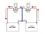
I'm not saying you're wrong and not trying to be argumentative, but, here's the thing--everyone learns a little differently. I like having things broken down into simplest terms--then build up to more complex. Add a little here, add a little there. I saw this as a 'simplest terms' explanation, AND, sound electrical theory. Here's what picture I believe he is trying to paint as a point of isolated ground theory:

wiring2.jpg

If one battery has its positive terminal connected to the negative terminal on the other, it IS a 24 Volt system. Of course, of the two remaining terminals, the "free" negative terminal is grounded (connected to the chassis), and the "free" positive one is connected to the rest of the electrical system.

This picture is "more" correct...That 12 Volts in red is what I believe he was referring to when he said

"To get 12 volt from the two 12 volt batteries (connected in series), a ground wire is put in between the two 12 volt batteries"

24volt.gif

I guess I can see now where it could be a LITTLE confusing to someone who has absolutely NO IDEA about electrical theory whatsoever...If so, I think it's because he just had a poor choice of words.


Last edited:
Top
AdBlock Detected

We get it, advertisements are annoying!

Sure, ad-blocking software does a great job at blocking ads, but it also blocks useful features of our website like our supporting vendors. Their ads help keep Steel Soldiers going. Please consider disabling your ad blockers for the site. Thanks!

I've Disabled AdBlock
No Thanks