-
Steel Soldiers now has a few new forums, read more about it at: New Munitions Forums!
Exciter Wire Question
- Thread starter AZDeuce
- Start date

More options
Who Replied?AZDeuce
Active member
- 484
- 38
- 28
- Location
- Tonopah, AZ
Warthog
Per your PM that my computer wouldn't let me respond to:
All 4 bulbs that are up in the left corner of the dash work, but none of them will work in the #2 position even though it shows 24V at that position. Is there anyway to trace the ground side of that circuit.
Something in the back of my mind told me that might be part of the problem and Mistaken1 or somebody mentioned it a few posts ago. But I have no idea how to test it, as I don't have the wiring scematic. And even if I did I might not be able to understand it.
What puzzles me, is after I sparked the voltmeter under the dash, I started the truck and the lights worked and I had 14.5V on each battery.......so "apparently" I didn't hurt anything when I arc'd it.
I then disconnected all the battery cables, and proeeded to install my relay plate and diagnosis plug, once done with that, I hooked up all the btry cables and saw nor heard any arcs/sparks when I hooked them up. So all "should" have been good!
However at that point I started the truck and now had NO #2 light, I checked the 24V fuse, and saw that it had blown........WHY? It wasn't blown after I started the truck after the spark incident!
I replaced that fuse and it has NOT blown sinse, and I got a 24V reading on the fuse box recepticle before I inserted the fuse.
Since I re-routed my exciter wires outside of the fuse box due to melted connectors, I added in-line fuses, they were ok.
But after all that, I still have no #2 light even though I have 24V at the #2 circuit, and I also have no power at the exciter wire.
The one thing I haven't looked at since the light quit working is the Voltmeter.....could I have ruined it with the spark, and it is part of the problem?
Anyway that's where I'm at (dead in the water). I need to know how to do a continuity check on the ground half of the #2 lights circuit.
And see if i have 24V at the voltmeter. I ASSume the key must be on to get 24v at the voltmeter, is this correct?
If so. could I attach a wire at the voltmeter, and run it to the exciter wire, and it would work when the key is on despite the light not working.....or is that a bad idea?
If it's a bad idea tell me why?
Thanks in advance
Use your voltmeter to check for voltage at the new inline fuse for the GEN2 exciter. You should see 24v.
If not we will have to trace backwards to find the problem,
The "ground half" of the GEN2 circuit is the alternator itself.
Here is the laymans path:
from the 24 Positive Terminal Block to the 24v fuse
from the 24v fuse via the orange wire to the "hot side" of the GEN2 bulb
thru the bulb and circuit board
from the circuit board via brown wire with red stripe to the GEN2 relay under the dash
when the key is on the GEN2 relay is energized and completes the GEN2 exciter path
from the GEN2 relay via the brown wire to GEN2 diode at the top of the dash, above the heater control
from the GEN2 diode via the brown wire to the firewall plug (where you bypassed)
from the firewall plug via the brown wire to the #1 pin of the GEN2 exciter plug
Last edited:
AZDeuce
Active member
- 484
- 38
- 28
- Location
- Tonopah, AZ
Warthog
Is that the relay on my sheet metal plate? I ask, as it appears there may be another relay, taped up to the wiring harness behind the heater controls.....besides the two small relays on the plate.
Also, I was able to run off the electrical part of the manual with the help of a computr savvy friend at work, however I never thought to get the scematics which were in a different location.
When I went back to get them the "Resources" section of SS was down. You could try sending the ones concernng this problem and I'll see if I'll get them and can open them, and then if they're big enough for me to see/make out.
Thanks
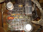
That third relay in the dash is for the Black Out Lights.
The two relays on the "plate" are the Voltmeter relay and the GEN2 relay
You can get the Tech Manuals at www.jatonksm35s.com
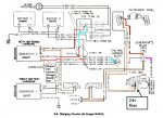
You will want Apendix F from the -20 manual or Apendix E from the -35 manual. They are the same in both. Diagram #9 shows the wiring for the alternators.
The two relays on the "plate" are the Voltmeter relay and the GEN2 relay
You can get the Tech Manuals at www.jatonksm35s.com
You will want Apendix F from the -20 manual or Apendix E from the -35 manual. They are the same in both. Diagram #9 shows the wiring for the alternators.
Attachments
-
 70.7 KB Views: 18
Last edited:
AZDeuce
Active member
- 484
- 38
- 28
- Location
- Tonopah, AZ
Warthog
That scematic worked perfectly and I was able to upsize it so I could read it.......COOL!
But I want to know what's that diode that appears to be coming off the fusebox at the bottom of that drawing, what's it do, and where exactly is it located on the truck?
Also with the key on, I checked the harness/fusebox side of both re-routed exciter wires at the in-line fuse half with the fuse removed on the Brown #1 exciter wire, I had power, but not on the #2 brown with a white stripe wire.
I have no reason to think any of my wiring got damaged in the last short incident, it was too fast, and there was no smell. So at this point I'm planning on buying two new relays and seeing if that fixes the problem.
That seems logical to me, how about you?
Okay, since you can get pictures, try this.
Check the fuse for the ignition circuit. It controls the GEN2 relay.
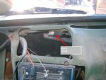
The diode that is in the GEN2 circuit is behind the heater control.
Check the fuse for the ignition circuit. It controls the GEN2 relay.
The diode that is in the GEN2 circuit is behind the heater control.
Attachments
-
 60.8 KB Views: 26
 -
 87.2 KB Views: 25
AZDeuce
Active member
- 484
- 38
- 28
- Location
- Tonopah, AZ
Warthog
All the fuses are good I've checked them all 3 times so far.
That Gen2 diode behind the heatr control is what I mistook for another relay. I think I'll see if I can get a new one at NAPA, thinking about new relays as well.
All the fuses are good I've checked them all 3 times so far.
That Gen2 diode behind the heatr control is what I mistook for another relay. I think I'll see if I can get a new one at NAPA, thinking about new relays as well.
Next step,
pull the GEN2 relay and check for voltage at the BROWN/RED wire of the plug. You should have 24v. And check for 12v at the pink/black wire with the key on.
And if that works, check for 24v at the diode with the key on. Check both sides of the diode.
You can check the diode with the ohmmeter. You will see zero ohms with the leads one way and infinity with the leads switched.
AZDeuce
Active member
- 484
- 38
- 28
- Location
- Tonopah, AZ
Warthog
Just checked the Gen2 diode with the key on there is power at the wire harness side of the plug, I did an Ohm test on the diode, and it showed numbers one way but not the other, so I assume that mean it's ok. I'll now go check the wires you mentioned at the relay plugs, and will report back
Just checked the Gen2 diode with the key on there is power at the wire harness side of the plug, I did an Ohm test on the diode, and it showed numbers one way but not the other, so I assume that mean it's ok. I'll now go check the wires you mentioned at the relay plugs, and will report back
AZDeuce
Active member
- 484
- 38
- 28
- Location
- Tonopah, AZ
Warthog
Just checked those wires and have both 12 and 24 V at that plug, only have 12V on the other plug. So does this mean the relay is bad? Or is it another issue?
Just checked those wires and have both 12 and 24 V at that plug, only have 12V on the other plug. So does this mean the relay is bad? Or is it another issue?
Help me here, which wires had voltage (colors) and what is the "other" plug?Warthog
Just checked those wires and have both 12 and 24 V at that plug, only have 12V on the other plug. So does this mean the relay is bad? Or is it another issue?
AZDeuce
Active member
- 484
- 38
- 28
- Location
- Tonopah, AZ
the brown and red wire and the pink and black wire, and the other relay plug in the sheet metal plate next to the Gen2 one.
AZDeuce
Active member
- 484
- 38
- 28
- Location
- Tonopah, AZ
That's 24V on the Brown/Red, and 12V on the pink/black. The other plug was the relay plug next to the Gen2 plug.
Next test,
open the hood and pull the two wire plug from GEN2.
With the key off, check the small red wire. Should have 24v. The brown wire should be zero volts.
With the key on, check the brown wire. It should be 24v
open the hood and pull the two wire plug from GEN2.
With the key off, check the small red wire. Should have 24v. The brown wire should be zero volts.
With the key on, check the brown wire. It should be 24v
AZDeuce
Active member
- 484
- 38
- 28
- Location
- Tonopah, AZ
Warthog
Already done that this morning, 24V on the red wire, but nothing on the brown wire with the key on or off.
Which I figured would happen since I still have no #2 dash light. What's next?
I think what ever is wrong is directly connected to that light not working, but I'm just guessing.
Already done that this morning, 24V on the red wire, but nothing on the brown wire with the key on or off.
Which I figured would happen since I still have no #2 dash light. What's next?
I think what ever is wrong is directly connected to that light not working, but I'm just guessing.
Todays exercise -
We have checked the path of the circuit and have narrowed the problem down to a small area.
Here is a summary:
1. from the 24 Positive Terminal Block to the 24v fuse - Good voltage
2. from the 24v fuse via the orange wire to the "hot side" of the GEN2 bulb - Good voltage
3. thru the bulb and circuit board - okay as we have voltage downstream
4. from the circuit board via brown wire with red stripe to the GEN2 relay under the dash - good voltage
5. when the key is on the GEN2 relay is energized and completes the GEN2 exciter path - appears okay as the next step has voltage
6. from the GEN2 relay via the brown wire to GEN2 diode at the top of the dash, above the heater control - Good voltage on one side and the diode is showing correct ohms - should be working
7. from the GEN2 diode via the brown wire to the firewall plug (where you bypassed) - no voltage ???
8. from the firewall plug via the brown wire to the #1 pin of the GEN2 exciter plug - no voltage - verified
------------------------------------
We have checked the circuit thru step 5. Picking up from where we left off yesterday at step 6 we need to check the voltage on both sides of the Diode and post the results.
The problem is between the diode and the alternator.
Check voltage at the diode, then check for voltage at the new inline fuse.
If both are working then check the connections at the new inline fuse.
AZDeuce
Active member
- 484
- 38
- 28
- Location
- Tonopah, AZ
Warthog
I'm at work and won't be able to respond back until I get home, but according to your last post I need to have the ignition key ON then check both sides of that diode I uncovered last night I would ASSume I'm going to put the red lead on both sides of the little diode, and put the black ground lead to the body some where correct?
If so, should I get power on both sides of the diode or just one? I'll report back later this evening with what I find.........THANKS!
- 114,343members
- 167,222threads
- 2,354,145posts
- 3,073online users