-
Steel Soldiers now has a few new forums, read more about it at: New Munitions Forums!
FDC bypass question
- Thread starter sammi91
- Start date

More options
Who Replied?mikey
Active member
- 759
- 40
- 28
- Location
- Lake Como, PA
The pump itself is 5-7psi.I would argue that the pressure from the in-tank pump is insufficient to properly test the FDC, it operates on about 20 psi IIRC.
The sealing surfaces are honed (?) to fit and hard particles (=rust) from the fuel tank especially will mar the surface.
The piston in the FDC moves very little when in use, but micron size grains of dirt will cause a leak when moved from start-up position.
As a precaution, I now have a magnetic in-line fuel filter in the system...
I read that from "Troubleshooting the Multifuel Engine" from JT's website.
- 10,349
- 94
- 48
- Location
- Meadows of Dan, Virginia
Right, and subtract a few psi from the drops across the filters along the way. If the piston doesn't leak in the "rest" position doesn't mean that it won't when in operating position.The pump itself is 5-7psi.
I read that from "Troubleshooting the Multifuel Engine" from JT's website.
I would recommend that an oil analysis is done every so often to find out what might be mixed in with the crankcase oil.
Filters and lines only drop pressure if there is flow going on, and in this test the flow rate is equal to the leakage, so almost non-existent.
If you read the sheets I copied from the manuals, they only test the FDC piston shaft for leakage in the rest position... and they use 10 PSI because the IP is on the test stand.... Could be the wrong thing to do, but that is what they recommend.
Because the piston shaft is a clearance seal, rather than a packing gland seal, leakage is proportional to the pressure applied. If 1 minute without a drip is ok at 10 PSI, 2 minutes without a drip will show the same thing at 5PSI.
I got the method of using the tank fuel pump pressure to test the FDC for leakage straight out of one of the TM's, or possibly one of the PS magazines, I will have to look and find it, I guess.
-Chuck
Last edited:
- 10,349
- 94
- 48
- Location
- Meadows of Dan, Virginia
Good point, but "with all lines intact", there will be flow, just check the return flow to the tank.Filters and lines only drop pressure if there is flow going on, and in this test the flow rate is equal to the leakage, so almost non-existent...
-Chuck
You are right, of course... I've got to remember to stop posting when I'm tired... The whole way the FDC works is by measuring the resistance of the fuel to flow through a controlled leak. However, a set of serviceable fuel filters is not going to drop the pressure on the output side of the filters enough to matter. My point still remains, you can do a close enough to the standard test stand test of FDC leakage using the in tank fuel pump. If you want to test under full pressure, do the same test only with the engine idling. Lifting the FDC to check its piston action while the engine is idling, is another standard test.Good point, but "with all lines intact", there will be flow, just check the return flow to the tank.
-Chuck
peashooter
Well-known member
- 1,039
- 210
- 63
- Location
- Hanover, minnesota
Is this statement right? I just bypassed my FDC and had lots of smoke so I turned the main adjustment counter-clockwise about 12-16 flats in the decrease fuel direction (I think, So fewer threads are showing anyway). I didn't touch the droop screw as mentioned. Am I reading this wrong or should I be turning up the fuel (so more threads are showing) and then possibly adjusting the droop screw down?There is a formula method for getting close to the correct fuel adjustment when the FDC is bypassed. That method is to adjust the nut on the compensator stop plate screw (smoke limit) 12 to 16 nut flats (sixths of a turn) clockwise (in the increase fuel direction), and to adjust the droop screw 1 to 2 turns clockwise(in the decrease fuel direction).
Rmtaunton
Well-known member
- 1,510
- 31
- 48
- Location
- Smyrna, ga
You are correct less threads less fuel , I want to say, 1.6 mm is stock, I will wait for G to step in with a picture, diagram, full color pie chart, and a better explanation than Einstein could give as he always does ") , I bet he has a graph on well endowed women who like guys with MV's . Still waiting to see that one. My search button must not be working right .
, I bet he has a graph on well endowed women who like guys with MV's . Still waiting to see that one. My search button must not be working right .
, I bet he has a graph on well endowed women who like guys with MV's . Still waiting to see that one. My search button must not be working right .- 3,024
- 230
- 63
- Location
- eldersburg maryland
while that statement MAY be correct, it seems to me that it would also be quite risky given you don't really know if things are set correctly to start with. you really need at least a boost gauge, just a pressure gauge that reads from 0 to 15 psi, and for stock performance manifold pressure at 2300 rpm wot should be 9 psi. this is quite conservative and you could go to 12 psi without a exhaust temp gauge for more power and worse mpg.Is this statement right? I just bypassed my FDC and had lots of smoke so I turned the main adjustment counter-clockwise about 12-16 flats in the decrease fuel direction (I think, So fewer threads are showing anyway). I didn't touch the droop screw as mentioned. Am I reading this wrong or should I be turning up the fuel (so more threads are showing) and then possibly adjusting the droop screw down?
tom
peashooter
Well-known member
- 1,039
- 210
- 63
- Location
- Hanover, minnesota
I guess I didn't mention it but I did know where things were set to start with, I wrote down how many turns in flats I did but didn't have it handy when I wrote the question. I also have a boost and EGT gauge. I have a good running truck now (it was before the FDC bypass too though) but the test drive after the bypass with fuel unchanged produced lots of smoke which is why I turned it down..... just got confused by the statement saying to turn it UP (clockwise) and then adjust the droop screw. The question was to mainly verify if that statement was correct or if it was reversed as it appeared to be.while that statement MAY be correct, it seems to me that it would also be quite risky given you don't really know if things are set correctly to start with. you really need at least a boost gauge, just a pressure gauge that reads from 0 to 15 psi, and for stock performance manifold pressure at 2300 rpm wot should be 9 psi. this is quite conservative and you could go to 12 psi without a exhaust temp gauge for more power and worse mpg.
tom
Last edited:
- 3,024
- 230
- 63
- Location
- eldersburg maryland
yes but the point i am making is where were things really set to start with? correctly? how would anyone really know? unless a pump shop had done it recently, no one knows what they have other than to assume that if the seals are still in place it is right, and with the mil 'mechanics' that may not be that often.
I got the "formula" from a couple of pages out the December 2002 issue of Military Vehicles Magazine, and the author, Pierre Jalving, got it out of one of the TM's that was issued after the ARMY fuel system was standardized on diesel/JP fuels.Is this statement right? I just bypassed my FDC and had lots of smoke so I turned the main adjustment counter-clockwise about 12-16 flats in the decrease fuel direction (I think, So fewer threads are showing anyway). I didn't touch the droop screw as mentioned. Am I reading this wrong or should I be turning up the fuel (so more threads are showing) and then possibly adjusting the droop screw down?
The author, Pierre Jalving, got confused when he wrote up his article, and gave instructions for disabling the FDC by rerouting the fuel lines so that it is bypassed, and then gave the instructions for making the adjustments for returning the FDC back to a normal un-bypassed state. When I typed in the instructions, I was obsessing over whether the correct adjustment direction was clockwise, or counter clockwise, given the instructions in the TM, and got it bass ackwards.
The correct answer is, bypassing the FDC makes it think that you are burning a thin fuel, like gasoline, which will cause the engine to be overfueled when using a thicker fuel, like diesel. So, you want to reduce the fuel rate by about 12-16 flats, which is 2 to 2-2/3 turns.
There really is more to bypassing the FDC than just bypassing it, and reducing the fuel.
The problem is, making such a large change in the fuel plate, will throw off the drop/droop adjustment.
When a governor equipped engine takes on a load, such as what happens when you go from level travel, to a slight hill, the governor will try to compensate by cranking up the fuel to the engine. The drop/droop adjustment determines whether the governor will: a) provide the exact right amount of fuel necessary to keep the RPM's constant, b) provide too little fuel and let the RPM's drop (droop), or c) provide too much fuel and make the RPM's speed up.
If you crank the throttle plate in, so that the fuel drops enough to compensate for the FDC being bypassed, you will screw up the drop/droop adjustment, so it needs to be compensated too. Depending on the model IP, it can be a screw adjustment, or a tab that needs bending.
What you will usually experience if you just crank the fuel down, and don't adjust the drop/droop, is the engine will stall when you let the engine go from heavy throttle back down to idle. And, you will also find that the engine doesn't want to start because when the engine isn't turning, the governor is in its full fuel starting position, which is affected by the drop/droop adjustment.
In any case, the "formula" method was a field expedient move, and was only supposed to be done in an emergency. The standard method required putting the bypassed IP on the test stand and resetting it for the new arrangement.
I would correct my original post to get the fuel adjustment in the right direction, but they turned off editing for that post before I first noticed my mistake.
-Chuck
Last edited:
- 3,024
- 230
- 63
- Location
- eldersburg maryland
yeah, after bypassing the FDC you almost always have to turn it down.
peashooter
Well-known member
- 1,039
- 210
- 63
- Location
- Hanover, minnesota
Thanks for the great clarification Stumps.I got the "formula" from a couple of pages out the December 2002 issue of Military Vehicles Magazine, and the author, Pierre Jalving, got it out of one of the TM's that was issued after the ARMY fuel system was standardized on diesel/JP fuels.
The author, Pierre Jalving, got confused when he wrote up his article, and gave instructions for disabling the FDC by rerouting the fuel lines so that it is bypassed, and then gave the instructions for making the adjustments for returning the FDC back to a normal un-bypassed state. When I typed in the instructions, I was obsessing over whether the correct adjustment direction was clockwise, or counter clockwise, given the instructions in the TM, and got it bass ackwards.
The correct answer is, bypassing the FDC makes it think that you are burning a thin fuel, like gasoline, which will cause the engine to be overfueled when using a thicker fuel, like diesel. So, you want to reduce the fuel rate by about 12-16 flats, which is 2 to 2-2/3 turns.
There really is more to bypassing the FDC than just bypassing it, and reducing the fuel.
The problem is, making such a large change in the fuel plate, will throw off the drop/droop adjustment.
When a governor equipped engine takes on a load, such as what happens when you go from level travel, to a slight hill, the governor will try to compensate by cranking up the fuel to the engine. The drop/droop adjustment determines whether the governor will: a) provide the exact right amount of fuel necessary to keep the RPM's constant, b) provide too little fuel and let the RPM's drop (droop), or c) provide too much fuel and make the RPM's speed up.
If you crank the throttle plate in, so that the fuel drops enough to compensate for the FDC being bypassed, you will screw up the drop/droop adjustment, so it needs to be compensated too. Depending on the model IP, it can be a screw adjustment, or a tab that needs bending.
What you will usually experience if you just crank the fuel down, and don't adjust the drop/droop, is the engine will stall when you let the engine go from heavy throttle back down to idle. And, you will also find that the engine doesn't want to start because when the engine isn't turning, the governor is in its full fuel starting position, which is affected by the drop/droop adjustment.
In any case, the "formula" method was a field expedient move, and was only supposed to be done in an emergency. The standard method required putting the bypassed IP on the test stand and resetting it for the new arrangement.
I would correct my original post to get the fuel adjustment in the right direction, but they turned off editing for that post before I first noticed my mistake.
-Chuck
I'm having a hard time telling from the pictures I'm looking at in the TM if there is a jamb nut on the Droop adjust set screw inside? If so the FDC top must come off to get to the jamb nut and adjust correct? I do have TM9-2910-226-34 open and am doing my best to comprehend it but at 200 pages and most all appearing to relate to adjusting this on a pump test stand, I'm having a hard time figuring out how to adjust the droop to increase my idle/low end fuel to make up for the FDC bypass changes.
- 7,426
- 2,538
- 113
- Location
- Interlachen Fl.
No jam nut on a droop screw Peashooter. I would use the TM trouble shooting 465 and use a boost gage as showen in the TM.
When bypassing the FDC the droop goes lower so clockwise will decrease. A 1/4 turn goes a long way. I feel if your going to bypass the FDC then a boost gage and pyro should be added so no matter if you want to go higher or lower on the main fuel you know where you are with the figures.
When bypassing the FDC the droop goes lower so clockwise will decrease. A 1/4 turn goes a long way. I feel if your going to bypass the FDC then a boost gage and pyro should be added so no matter if you want to go higher or lower on the main fuel you know where you are with the figures.
Last edited:
peashooter
Well-known member
- 1,039
- 210
- 63
- Location
- Hanover, minnesota
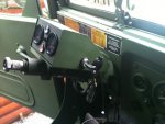
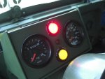
Thanks Floridianson! I'll download the 465 troubleshooting. I've got the boost & pyro already and have been turning my fuel down a few times now based on where I want it to be egt wise. I did notice slightly more difficult starts so that's the reason for the droop questions. So I should be good to go from the sounds of it.No jam nut on a droop screw Peashooter. I would use the TM trouble shooting 465 and use a boost gage as showen in the TM.
When bypassing the FDC the droop goes lower so clockwise will decrease. A 1/4 turn goes a long way. I feel if your going to bypass the FDC then a boost gage and pyro should be added so no matter if you want to go higher or lower on the main fuel you know where you are with the figures.
Thanks for the help all.
Attachments
-
 40.6 KB Views: 39
 -
 41.9 KB Views: 36
- 7,426
- 2,538
- 113
- Location
- Interlachen Fl.
Nice set up with easy to read gages Peashooter like I need in my old age. As per tm droop screw controls how much fuel between 1600 and 2000 rpm. No need to waist fuel down low just need it on the top end.
- 114,408members
- 167,297threads
- 2,355,043posts
- 1,057online users