• Steel Soldiers now has a few new forums, read more about it at: New Munitions Forums!

  • Microsoft MSN, Live, Hotmail, Outlook email users may not be receiving emails. We are working to resolve this issue. Please add support@steelsoldiers.com to your trusted contacts.

Fixing the 1998 HMMWV

mrandig

Active member
92
122
33
Location
Houston, TX
Heater / Defroster Duct Removal.

Based on the abject failures of earlier this week and last, I decided to focus less on taking pictures. Why bother if it's not going to work out, am I right?

That being said, one thing led to another, and now all of the heater and defroster ductwork is being replaced. This is a good thing, as the cabin would just fill up with dust (sand) anytime either were turned on.

Any pictures I have then are post-mortem, rather than in-process, but I'll explain the best I can.


The first step is to remove the access cover on the passenger side. The fasteners don't quite match what's shown in the manuals, but mine was two bolts at the top right, and one screw at the lower left.
20250418-084512-004.jpg

Once the cover is removed, you'll have full access to the entire unit, including both duct assemblies and all of the flex ducts. Obviously, I took this picture after the flex ducts were removed.

The bug sprayer is filled with soapy water, as I like to clean as I go.
20250418-084519-005.jpg

The right-hand defroster duct and nozzle are pretty easy going. Just unscrew the lower clamp and wiggle the nozzle out of its channel.
20250418-084546-006.jpg

The large heater duct which bridges across the doghouse will need to be removed. For me, this needed to be replaced anyways. Mine didn't have any clamps, so it was just a slip-on/slip-off situation.
20250418-084606-008.jpg

Once the heater duct is out of the way, there is a body panel and a retaining strip that will need to be removed from under the windshield frame. There's a total of eight screws inside the cabin, and three bolts in the engine compartment.
20250418-084620-009.jpg

Once the body panel is removed, there will be some insulation strips that will also need to removed. In my case, they just fell out, so I didn't need to do much. The question is, how we will put this back together once the time comes to reinstall.

My money is on double sided tape, but we'll see.
20250418-084641-011.jpg.

The left-hand duct and nozzle are almost more trouble than it's worth. From the doghouse side, pulling on the duct will get you a big handful of shredded duct work, but removal of the nozzle requires access from behind the dash.
20250418-084627-010.jpg

You're going to need to drop the steering column for this part. Also, I had already managed to break both my turn signal lever and air restriction gauge during my earlier exploits, so be careful.
20250418-084712-013.jpg

Once the steering column is dropped, you'll be able to access the retaining pin that holds in the left nozzle. It's still pretty tight to get to, but not impossible.
20250418-083636-001.jpg

I ended up using an automotive trim tool and was able to get the retaining pin out, in mostly useable condition, for re-installation.
20250418-084659-012.jpg

Retaining pin removed.

Considering how over-done, over-thought, and over-priced everything else is, it's like they got close to the end of building this truck and just said screw it. "We'll just use the interior trim pieces from a Chevy Cruze".
20250418-083731-002.jpg

Left duct finally removed. It's a funny process getting this nozzle out, as you have to turn, twist, push, and then pull a few times, but eventually it does come out. Supposedly it should be turned clockwise to install, counterclockwise to remove. Supposedly.
20250418-084101-003.jpg

Once everything is cleaned up and organized, we'll start putting in the new parts; hopefully later today. More updates to follow...
20250418-084556-007.jpg
 
Last edited:

mrandig

Active member
92
122
33
Location
Houston, TX
None of this was on my original to-do list.

Actually, it looks worse than it is. With some luck and a little bit of time, this should be all back together by tomorrow.

A few updates to follow shortly...
20250418-124301-016.jpg
 

mrandig

Active member
92
122
33
Location
Houston, TX
Replaced the fuel gauge with a Faria one this evening. This was absolutely one of the issues that was causing problems.

Notice that it's pegged to the far right with power and ground connected, but without the sending unit attached. This is exactly what this gauge should be doing.

It's frustrating however that this gauge is scratched right from the box, but at least it's only cosmetic; we'll deal with that next week.
20250418-202742-017.jpg

The new gauge seems to be reading pretty high, but the tank looked very full also. I'm not sure if this reading is correct, but at least now, if there is an issue, I can focus solely on the fuel sender.
20250418-202940-018.jpg

While I was changing out the fuel gauge, I also replaced the gaskets on the dash lights. I didn't take a picture here, but it definitely makes a difference with the gauge illumination.
20250418-203332-019.jpg

All done with the dash and gauges. We'll get this back in for good once the flex ducts are installed tomorrow.
20250418-203419-020.jpg
 
Last edited:

mrandig

Active member
92
122
33
Location
Houston, TX
For my last item this evening, I want to knock out the brake warning indicator that has been giving me problems. Actually, it hasn't been giving me anything, which is why I need to change it.

Brake warning indicator.

Here's my problem-child. I already removed the air restriction indictor so I could gain access to the lamp wiring.
20250418-203809-022.jpg

Warning light disconnected.

Disconnecting the lamp and testing it is a little tricky, as there's not really room for two hands, but it's possible. Looking for a full 24v on this circuit with the parking brake engaged. Alternately, instead of engaging the parking brake, I could've grounded the switch at the proportioning valve, with the same result.
20250418-204514-023.jpg

Results are in, and they are correct. We've got 24v when the parking brake is engaged, 0v when it's not.

There's nothing wrong here except for a bad light.
20250418-204519-024.jpg

Light Replacement.

This was another piece that was tricky to replace but worked out in the end. The space behind this lamp is really narrow, and it's not a matter of reaching up and just plugging in the light.

I ended up sliding the lamp into place from the open dash panel (not shown). There's a channel behind the dash face, and the light can just be slid sideways right-to-left until it's in the correct location. It's just two self-tapping screws that hold it in place. The connections are hard to make with one hand, but it just takes a little patience.
20250418-211515-025.jpg

Success!
 
Last edited:

mrandig

Active member
92
122
33
Location
Houston, TX
This weekend is going to be lit. As my youngsters would say...

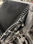
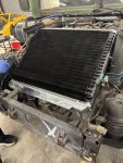
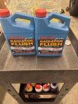
It's Easter weekend and I've got a box of cleaner and radiator paint.
20250418-123108-014.jpg

20250418-123117-015.jpg
They even gave me coupons. I can get ground beef for life, discounts on deodorant and ED pills. Interesting choice of combinations, but I guess I can see how at least two of those go together.

Once the flex ducts are replaced and the interior has been re-installed, we'll come back to this.
 

mrandig

Active member
92
122
33
Location
Houston, TX
Just wanted to follow up on an earlier post to this thread. Way back when, in post #6, I had questions regarding the driver's side mirror assembly.

This mirror has a low mounting point, rather than mounting at an equal height to the passenger side. The latter (equal height) configuration seems to be more common, and this truck does have those riv-nuts installed also (damaged however). My eyeballs aren't calibrated, but it looks like it sits about 6" lower.

View attachment 944347

View attachment 944348


I've researched this to the point that I don't even remember where I looked or what I've come up with as a result.

The -24P gives me 5 different listings for mirrors; none are specific to an M1123 A2 (UOC NNN). The -24P does say however, that the mirror currently installed is the correct part number for a "lower mount" mirror.
View attachment 944353

Neither the -20 nor -24P are particularly clear on how this is supposed to look once installed. The -10 however, does have this...
View attachment 944352


So, back to my original question - does this mirror look like it's installed correctly?

Thanks in advance.
I was never able to get my question about the lowered driver's mirror fully answered, so I just decided to replace. Enough time has already been wasted, and I didn't want to lose any more.

The new driver's mirror is black instead of green, but it is pretty. The was definitely something that was cattywampus (incorrect) with the first one.

Here's the original:
20250419-140539-002.jpg

The new mirror sits in the same "low" position, but it now looks intentional. It doesn't have to be adjusted in all sorts of weird angles to be useable, like before.
20250419-140546-003.jpg

To be totally honest, the original riv-nuts in the frame are wasted, so it was just easier to leave the mirror in the position it was at. Otherwise, I probably would have raised the driver's mirror to be at the same height as the passenger's.

Before:
20250104-101025-010.jpg

After:
20250419-140553-004.jpg

I'll take the cover and protective packaging off it at some point. It's not like I'm going anywhere in this truck over the next few days. It's just one less thing to get scratched at the moment.
20250419-140558-005.jpg

Check off another task as completed.
 
Last edited:

mrandig

Active member
92
122
33
Location
Houston, TX
Most of the tasks I'd been recording over the last day or so, were done while also working on the heater / defrost flex ducts. Needless to say, there's a few steps to getting these reconditioned, before even trying to get them back into the truck.

20250418-084546-006.jpg

With all of the flex duct removed, the first thing was to figure out the correct length(s) I was going to need.
20250419-141036-008.jpg

Next, I needed to remove the old nozzles, as these will be re-used. The hose is glued on, but you can use a peeling action to get these off easily.
20250419-141255-011.jpg

20250419-141058-009.jpg

20250419-141112-010.jpg

With the old hose removed, clean the nozzle ends to remove any dirt, debris or loose glue.
20250419-141504-012.jpg

I'm going to use some adhesive sealant RTV. It happens to be what I have around, but also seems to be similar to what was originally specified. This particular type of RTV (#80080) is a general adhesive; it's not for engine use. Basically, it's glue for adults.

You probably won't need such a big tube, or the caulking gun, but it is fun to have. If I got my wife a vacuum for her birthday, she'd probably be pretty p****d-off. If I got a new caulking gun with all the fancy features for my birthday, I'd actually be pretty thrilled.
20250419-142043-013.jpg

There doesn't need to be much glue, as the connection will be very tight. A thin bead should be fine.
20250419-142120-014.jpg

Once applied, gently twist the new hose over the nozzle. As I went, I kept turning the hose clockwise to install, but I'm sure direction doesn't matter.
20250419-142410-016.jpg

Once the hose is fully seated, the assembly will need to cure for 24hrs. For a little added security here, I also added a zip tie.
20250419-142303-015.jpg

Here's everything completed.
20250419-143513-017.jpg

Just as a side note, if you don't have a pair of medical scissors, get some. Steal some if you need to. They're absolutely one of the best tools that I own. Any cutting I had to do here was with these, and they're fearless.
20250419-143519-018.jpg

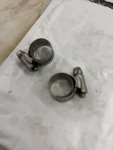
Any finally, the clamps go off the ultrasonic cleaning bath.
20250419-143537-019.jpg

We'll catch back up on this task once everything has had a chance to cure, and once I'm convinced it's not going to fall apart during installation.
 
Last edited:

mrandig

Active member
92
122
33
Location
Houston, TX
It seems like the ultrasonic cleaner has been running for several weeks non-stop.

Every part gets bagged, tagged, and cleaned. If it doesn't go back on immediately, it gets filed away so I can find it easily later on.

Heater and defrost ducts are going back in tonight.
20250421-184315-009.jpg
 

mrandig

Active member
92
122
33
Location
Houston, TX
Defroster flex ducts - installation

First things first, I'm going to try to blow out any dirt / sand from behind the dash, so these nice new ducts maybe stay that way for a while. I have cleaned this truck so many times, and it never seems to get better.

Drivers side:
20250421-182906-001.jpg

Passenger side:
20250421-182915-002.jpg

The driver's side duct is fairly long, so I'm going to connect it to the diverter first, then across the doghouse, then place the nozzle into position behind the dash cluster.
20250421-183211-003.jpg

Insert the driver side nozzle into the dash channel. It should be relatively flat. Rotate clockwise once it's all the way in.
20250421-183331-004.jpg

There's really not much to show here in pictures.
20250421-183345-005.jpg

That stupid little pin will keep the nozzle in place on the driver's side.
20250421-183739-006.jpg

Here's the driver's side attached at the diverter. I'll install the clamps here in a minute, once I know everything is going to fit correctly.
20250421-183822-007.jpg

The passenger's side is the easiest; it's not a particularly long run of tubing. Insert the nozzle into the channel, then connect at the diverter.
20250421-183907-008.jpg

Here's both ducts with clamps installed.
20250421-191107-010.jpg

Finally, there's a third piece of tubing here. I guess this is technically considered part of the heater, as it runs directly to the floor, where it is held in place by a zip-tie.
1745287426577.png

After this picture was taken, I did adjust the clamps a bit, as I didn't like them poking into the new tubing.
20250421-191401-011.jpg

And that should do it.
20250421-211357-013.jpg

Time to function test. Works perfectly.
20250421-191622-012.jpg

Installation isn't complete just yet, as it's all not back together, but the main parts are installed and working correctly.

We'll wrap up the rest of this either tonight or tomorrow morning; there probably won't be many more pics, as it's hard to see much of anything.
 
Last edited:

mrandig

Active member
92
122
33
Location
Houston, TX
Here's a final pic of the duct work before the cover goes back on.
20250423-173513-001.jpg

It may not be noticeable in the lower left corner, but since I was pulling everything out, I also took a moment to install an auxiliary grounding kit. Only added a few extra minutes to the day.
 

mrandig

Active member
92
122
33
Location
Houston, TX
A few pics of the auxiliary grounding harness.

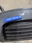
This is the harness from Kascar (#535-A1). There are already several posts on this forum discussing this kit, so I'll be brief. I don't feel like debating electrical theory, so I won't. I just like lots of grounds, and this was easier than making them myself.
20250422-031527-005.jpg

Each connection is labeled A thru E.
20250422-031605-006.jpg

Instructions are included.
1745448537215.png

Lug "A" connects to the firewall, above the fuel filter.

Inside the firewall.
20250422-030616-001.jpg

Outside the firewall, behind the heater duct (hose removed).
20250422-030630-002.jpg

Lug "A" connected.
20250423-173604-003.jpg

Lug "B" connects to the alternator.
20250423-173629-005.jpg

Lug "C" connects to the Protective Control Box.
20250423-173620-004.jpg

Lug "D" connects to the starter.
OOPS. I will need to edit once I get pic.

Lug "E" connects to the rear of the left cylinder head.
20250423-173528-002.jpg

That is all.
 
Last edited:

mrandig

Active member
92
122
33
Location
Houston, TX
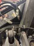
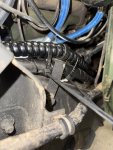
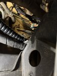
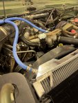
Now I need to sort the hoses, cables, and other things that had been running above and across the firewall.

Not looking forward to playing a game of "what's this hose for".
20250423-173710-006.jpg
 
Top