• Steel Soldiers now has a few new forums, read more about it at: New Munitions Forums!

  • Microsoft MSN, Live, Hotmail, Outlook email users may not be receiving emails. We are working to resolve this issue. Please add support@steelsoldiers.com to your trusted contacts.

Fmtv no more dual voltage

Ronmar

Well-known member
3,881
7,547
113
Location
Port angeles wa
If you are missing the other smaller device in the above pic that Ohiobenz posted, that is an instrunment shunt, used to measure current flow. It is placed in the main ground line between battery and starter and can measure crank current and total alternator output back into the batteries. The two large leads that attach to it can simply be connected together and insulated…

6025FB78-1BB7-4E38-B2B1-9B7B5AB550A6.jpeg
 

astacey1403

Member
27
40
13
Location
Leadville Colorado
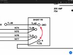
Yea, that is the polarity protection box. It is just a set of diodes that prevents batteries that are connected backwards from doing damage in the cab. To get you off the lot, it can be bypassed, just don’t hook up your batteries backwards.

In the attached pic, connect the wires circled in red together(12v batt, alternator and load to cab) and insulate the connection. Then repeat the process for the wires in the green circle.

View attachment 868480
This diagram helps out a bunch. I figured I could bypass the system just was not sure. I will be attempting this when I go back to work on the truck. When I first went out to work on the truck I only had 2 new batteries with me in hoping that the truck only needed the 24v system to start but I do not think this is the case. I think the ignition system is a 12v energized solenoid for 24v starting. I had some members of this forum help me get the truck moved to an RV storage lot for the time being.
 

Ronmar

Well-known member
3,881
7,547
113
Location
Port angeles wa
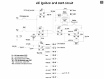
Most everything except the lighting is 24V, but the main ignition switch uses 12V to energize the control power relay (K02) that powers all the 24V circuits… Here is an abbreviated start circuit diagram I condensed from the A0 tech manual. You might need this When it comes time to start it:)

Probably should start a new discussion on any further adventures, as we just hijacked the heck out of this one… Good Luck

B1B77AD0-309F-44F7-A65E-24C06249AFEA.png
 

Ohiobenz

Well-known member
Supporting Vendor
464
267
63
Location
Seville, OH
Yup that picture you sent is definitely what is missing the smaller bridge is there but that larger PPD is missing. ( sorry i am not following the HMU and number set you listed in this message )
Hit Me Up...

Its my phone phonetically lol - stops bots from reading it.
Follow Ronmar's instructions on connecting your cables.
If you can give me a call on the 2 parts i can ship pretty quick, they're no use to me so reasonably priced.
 
Top
AdBlock Detected

We get it, advertisements are annoying!

Sure, ad-blocking software does a great job at blocking ads, but it also blocks useful features of our website like our supporting vendors. Their ads help keep Steel Soldiers going. Please consider disabling your ad blockers for the site. Thanks!

I've Disabled AdBlock
No Thanks