• Steel Soldiers now has a few new forums, read more about it at: New Munitions Forums!

  • Microsoft MSN, Live, Hotmail, Outlook email users may not be receiving emails. We are working to resolve this issue. Please add support@steelsoldiers.com to your trusted contacts.


Glow Plug - By Pass Help

69
1
6
Location
Hurst Texas
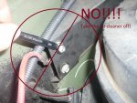
I have an 1986 M1008 CUCV. My truck has already been converted to bypass the glow plug controller. I have had an extermly difficult time getting the truck to start now that it is colder and I am blowing the manual switches. I can push the manual switch for 10 seconds, wait 30, hold 10 seconds, wait 30, hold 10 seconds, wait 30 and truck may turn over but will die. Next hold for 5-7 seconds wait 21 seconds, hold 7 seconds, wait 21 seconds, hold 7 seconds and it may start. This last time I blew the switch.

So I replaced all the glow plugs and now I have questions about how the wiring is supposed to be for the bypass. I do not have a glow plug controller at all. So I have to work with what I have.

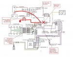
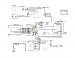
I took the glow plug diagram from the TM and color coded it and I will upload it along with this post.

I put a new 50 amp switch in, and a 30 amp fuse. I blow the 30 amp fuse within 1-2 seconds of turning on the switch.

I get the same results when I leave the 24v resistor going to the glow plug relay or if I bypass the resistor and use 12v from the neg of the back battery.

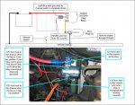
I can take a stab at describing the configuration I have... but it would be easier to draw it out. IF someone who has done this can use my diagram that I am attaching and tell me what to wire the switch too that would be helpful. If possible I would like to be able to have a fuse protecting the plugs from over charging and/or blowing the manual switch.
 

Attachments

mistaken1

New member
1,467
6
0
Location
Kansas City, KS
Your switch should connect one of the small terminals on the relay to ground (chassis) the other small terminal has 12V when the key is on.

One of the large terminals connects to the 12V source (negative of the back battery) and the other larger terminal connects to the glow plugs.

You should not be destroying switches or 30A fuses activating the glow plug relay.
 

mistaken1

New member
1,467
6
0
Location
Kansas City, KS
The glow plug relay in this system needs to have an isolated coil.

The coil receives voltage when the key is on and the control (manual switch or controller) grounds the other side of the relay coil to complete the circuit and energize the coil.
 

Attachments

69
1
6
Location
Hurst Texas
Everything in your drawing I have done... but I don't understand the switch part... Are you saying to take the light blue from the glow plug module plug connect it to a manual switch and then the other pole of the switch run it to a ground and that will complete the circuit when the switch is in the "On" position? This will complete the circuit and charge the glow plugs?

My current config is sooo messed up!! Mine has the the 12v from the top pole coming into the truck, then to a manual switch and then back to the bottom pole. UGH... surprised I haven't burned up the truck!
 
Last edited:
69
1
6
Location
Hurst Texas
I tapped into the light blue wire at the glow plug module inside the cab.

I ran that new tap to the manual toggle switch on one terminal and the other terminal of the switch I ran to the ground that the dash gauges use on the inside of the truck right above the side air vent.

I hooked up a 4 gauge red wire from the neg post of the second battery to the top post of the glow plug relay. I connected the orange 14 guage .5 ORN-509B on diagram to the bottom post with the two orange 12/10 guage ORN 503B (SXL) wires. The pink/blk ignition feed is hooked up to the bottom left post on the glow plug relay.

With the batteries hooked up and a single 4gauge wire going to the top post of the glow plug relay I get the 12.x volts.

If I turn the ignition switch on the light blue on the top left side post of the glow plug relay shows about 1.4 to 1.7 volts. The pink/blk on the bottom left side post of the glow plug relay shows 12.x volts.

If I turn the manual switch on I get 0v on the bottom post of the glow plug relay.

So my question is two fold... does it sound like I have everything hooked up correctly and am I getting the correct voltages on everything but the bottom post?

Since I am getting 0v on the bottom post of the glow plug relay does that mean I have a bad glow plug relay?
 

mistaken1

New member
1,467
6
0
Location
Kansas City, KS
I tapped into the light blue wire at the glow plug module inside the cab.

I ran that new tap to the manual toggle switch on one terminal and the other terminal of the switch I ran to the ground that the dash gauges use on the inside of the truck right above the side air vent.

I hooked up a 4 gauge red wire from the neg post of the second battery to the top post of the glow plug relay. I connected the orange 14 guage .5 ORN-509B on diagram to the bottom post with the two orange 12/10 guage ORN 503B (SXL) wires. The pink/blk ignition feed is hooked up to the bottom left post on the glow plug relay.

With the batteries hooked up and a single 4gauge wire going to the top post of the glow plug relay I get the 12.x volts.

If I turn the ignition switch on the light blue on the top left side post of the glow plug relay shows about 1.4 to 1.7 volts. The pink/blk on the bottom left side post of the glow plug relay shows 12.x volts.

If I turn the manual switch on I get 0v on the bottom post of the glow plug relay.

So my question is two fold... does it sound like I have everything hooked up correctly and am I getting the correct voltages on everything but the bottom post?

Since I am getting 0v on the bottom post of the glow plug relay does that mean I have a bad glow plug relay?
Sounds like your relay is bad. You should see 12V at both sides of the coil with the key on and then when you close the switch to ground the blue wire you should see 12V at the orange wires.
 

Attachments

69
1
6
Location
Hurst Texas
UGH... :x
I switched out the glow plug relay with the Napa part ST85. (it actually makes note on the instructions that it was used for glow plug relay's for Dodge trucks 78-80)

I left everything as it was described in the previous post. Which matches the diagram you just posted. The relay looks like yours now btw... I had the other one that was black and hung the other way.

With the key off... I get 12.x volts to the top. (just like the diagram)
with the key on and the manual switch in the cab on off... I get .7 to .9 volts on the top side blue and 12.x on the side with the pink. The orange shows 12.x volts!! Not good.

I move the manual switch into the other position and get the same results.... not good!

So I remove the ground all together so there is no ground and I get 12.x volts at the blue and 12.x volts at the pink and 0 volts at the orange.

So I am thinking my manual switch is bad. I pull out the spare that I bought and I get the same results... regardless of which position of the manual switch is in (On/Off) I get .7v at the blue and 12.x volts at the orange.

I have had the switch installed the 1st time so it may have been grounded to the metal dash... but the second time when I changed out the manual switch I left it hanging loose.

The manual switch I am using is a 50 amp toggle switch with two poles.

When my wife gets home, I will remove the switch all together and have her hold the two blue to the ground and see if it works like it should....

It doesn't make sense.... regardless of the position of the switch its grounding the circuit. Am I missing something?
 

davidkroberts

Active member
1,453
22
38
Location
west tennessee
Are you getting air in your fuel lines? Might be another problem not related to your GP's at all. As your truck sits it may be loosing prime somehow and causing the hard starting when cold
 

bubba_got_you

New member
1,175
6
0
Location
st,petersburg Florida
[FONT=&quot]Here is what I did. Take an old ford relay (napa# MPE ST81SB) and hook the wires going to the glow plugs to one post and 12v to the other then use a switch and have one wire going from a 12v source (I just used the 12v side of the relay) and the other wire from the switch to the small terminal on the relay marked with a S. this will work if you do it the way I told you and it will work every time(it does for me).
[/FONT]
 
69
1
6
Location
Hurst Texas
The relay works like it is supposed to. You ground the blue and you get a drop in voltage and you get it 12.x volts out the bottom terminal with the orange wires to the glow plugs.

The wife still isnt home... but I turned the key on, touched the blue to a ground and held it for 10 seconds... let go counted to 30 and then held it again for 10 seconds and it started right up.

So I just need to figure out what is wrong with the manual switches.
 

mistaken1

New member
1,467
6
0
Location
Kansas City, KS
The relay works like it is supposed to. You ground the blue and you get a drop in voltage and you get it 12.x volts out the bottom terminal with the orange wires to the glow plugs.

The wife still isnt home... but I turned the key on, touched the blue to a ground and held it for 10 seconds... let go counted to 30 and then held it again for 10 seconds and it started right up.

So I just need to figure out what is wrong with the manual switches.
Did you hear the relay pull in and drop out as you grounded and and ungrounded the blue wire?

Perhaps it is the double pole that is throwing your wiring off? The only current that passes through the switch is that needed to energize the coil, it is not much.

A simple 10A or 15A single pole switch should work, momentary contact is better than a held contact. There should be two terminals on the switch, one gets the blue wire from the relay and the other one gets the wire going to your ground spade under the dash.
 
69
1
6
Location
Hurst Texas
Thread: Glow Plug - By Pass Help

May I inquire as to why you "let go counted to 30 " ?
I am not sure how long you can hold current to a glow plug. My old setup ran the 24volts to the inside of the truck to a switch, then to the bottom pole on the relay. If I held the switch down too long then it blew out the switch. Plus I just spent $100 on glow plugs... I don't want to burn them out.

So basically I don't have a base line for how long you hold the switch in and how long the plugs can remain hot constantly.
 
69
1
6
Location
Hurst Texas
I did not hear anything... but I have bad hearing so it may have made a noise and I just did not hear it. I will get a new single pole switch tomorrow and try that.

Thanks again for all your help working through this. I do wish all these diagrams would go in a sticky some where. You did a real good job of explaining with the diagrams.
 

mistaken1

New member
1,467
6
0
Location
Kansas City, KS
My old setup ran the 24volts to the inside of the truck to a switch, then to the bottom pole on the relay. If I held the switch down too long then it blew out the switch. Plus I just spent $100 on glow plugs... I don't want to burn them out.
So it was switching the entire glow plug load.

A full set of functioning glow plugs (assuming 1.5 Ohms per plug) will draw approximately 80A at 12V. If that setup sent 24V to the glow plugs by bypassing the resistor then the current draw would be half that at 40A but the glow plugs would see 24V and burn out quickly.

The relay is nothing more than a remote controlled switch. In this case it allows switching of the large glow plug load with a small switch in the cabin.
 

doghead

4 Star General /Moderator
Staff member
Super Moderator
Steel Soldiers Supporter
26,247
1,168
113
Location
NY
nice diagram btw... I wish all these pictures would end up in a sticky!
All the schematics are in the -20TM. You could use them to make any modification to your stock GP system.

No sticky, especially for a thread where the op is clearly beyond his understanding of basic electronics, and the way you choose to solve your issue is not "standard"(there are several ways to reconfigure the GP to manually operate).

Your system could have been modified much easier and this been posted in many other threads.

I think Mistaken1 is doing a great job helping you(although I would have recommended you do it differently). That is why I didn't respond before this post.

I was only going to address the comment about making this a sticky, but I just had to go on... 2cents
 

mistaken1

New member
1,467
6
0
Location
Kansas City, KS
Doghead you are right, these diagrams are not designed to show exactly how to do a 12V conversion but just to explain the most basic circuit for how the glow plug relay works.

I see now how others could take the connections shown directly from the battery literally and try to wire things that way.

Not knowing what was done to his truck to begin with I was trying to simplify the circuit as it centers around the glow plug relay.

Note to all:

These diagrams are just to illustrate the basic glow plug relay circuit and should not be taken literally as the way to actually wire a 12V glow plug conversion.

There are many threads on the site that describe where to get the 12V feed for the glow plug relay power terminal and how to manually or automatically control the glow plug relay. These are proven, reliable methods of re-powering the glow plug relay for 12V glow plug operation and should be followed.

The diagrams in this post are simply for understanding the basic circuit and troubleshooting this individual situation.
 

top_prop

Member
243
8
18
Location
Suffolk, VA
I just completed a 12v bypass on my M1009. The military system was running fine since I started driving it in June, but I felt it would be insurance to run AC60G's and I'm planning an Air Conditioning Install this winter as I live in the deep south. So eventually the entire 24v system will go and the rear battery will be moved to the driver side. I searched high and low and haven't found one comprehensive thread, so I figured I'd post my pics here as this thread has good diagrams.

Here's what I did (and I'm a newbie shade tree mechanic... use this info at your own peril).

1. Chocked the wheels.
2. Removed the front battery negative terminal
3. Removed the rear battery positive terminal
4. Removed the cover for the 24V bus and removed the lead that ran to the resister behind the air cleaner
5. Removed the lead from the resister to the Glow Plug relay at the relay
 

Attachments

Last edited:
Top
AdBlock Detected

We get it, advertisements are annoying!

Sure, ad-blocking software does a great job at blocking ads, but it also blocks useful features of our website like our supporting vendors. Their ads help keep Steel Soldiers going. Please consider disabling your ad blockers for the site. Thanks!

I've Disabled AdBlock
No Thanks