• Steel Soldiers now has a few new forums, read more about it at: New Munitions Forums!

  • Microsoft MSN, Live, Hotmail, Outlook email users may not be receiving emails. We are working to resolve this issue. Please add support@steelsoldiers.com to your trusted contacts.

glow plug system troubles

blindowner

New member
17
0
1
Location
North Augusta, SC, USA
Hello,
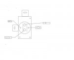
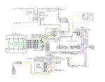
Summing up my gp system is simple, it has never worked properly. For the few times my cucv has run, I have used a bypass switch that connected the 12 volt terminal block to the lower terminal on the gp relay. Using the "wire color/key position" diagnostic from the tm 9-2320-289-20 I concluded that the temp sensor was bad and replaced it. When that didn't fix it, I decided that the module was bad and replaced it with a new one from antennaclimber, obviously, that didn't fix it either. One more thing or two of merit to mention, the gp relay is a Ford relay and the last test in the previously mentioned diagnostic was 4 ohm's instead of the required 6-10 ohm's but because of the fact that the relay isn't stock, I thought the variance acceptable. That sums it up, as always any help,tips,or questions are greatly appreciated.

Blindowner
 

doghead

4 Star General /Moderator
Staff member
Super Moderator
Steel Soldiers Supporter
26,247
1,172
113
Location
NY
A "Ford" relay will not work.
 

blindowner

New member
17
0
1
Location
North Augusta, SC, USA
hopes for a solution

Hello,
This may sound completely ignorant, but I read that certain Ford relay's (napa number gpr-109) can be used as a replacement. This relay has two signal wires, positive and negative, so the relay is not grounded. On a seperate note, the module has three led's to indicate what the module is doing: one of them indicates power to the module, another led indicates power to the wait light, and the last led shows whether the relay is being activated. Two of these led's are on at startup with the engine cold, specifically, the led's indicating power and the wait light being on, however the led that indicates the relay being turned on is off. I hope that this gives the puzzle pieces required to find the solution.

Blindowner.
 

mistaken1

New member
1,467
6
0
Location
Kansas City, KS
The GP has two coil terminals. One gets power anytime the key is on from the pink/black wire (do you have 12.x volts there when the key is on?).

The other terminal runs to the module (on the light blue wire) which grounds that lead to energize the GP relay.

Show us a picture of your relay and tell us what color wires are on each terminal.

I have used a bypass switch that connected the 12 volt terminal block to the lower terminal on the gp relay.
Without knowing what wire colors are connected to what the above sentence makes it sound as if your push button was sending 12V to a relay that already had 12V (relay will not activate) or was sending 12V to the normal 12V side of a relay that is not grounded (relay will not activate).

Contact antennaclimber and see what conditions are needed for the GP relay energized LED to activate. Will that LED light up anytime the card grounds the GP relay or will the LED only light when current flows through that circuit? IOW does the LED indicate the card function only or does it indicate successful card/relay function?
 

blindowner

New member
17
0
1
Location
North Augusta, SC, USA
Good Day,
To answer your first question, the voltage on the pink/black wire at the relay with the ignition switch on and the engine cold is 11.56 volts. I would also like to correct my statement that you quoted, what I was referring by the lower teminal was the main power feed to the glow plugs. The photo that I included is a crude representation of a diagram in "Haynes Diesel Engine Repair Manual"and, I'm sorry that I can't take a picture of the relay because I don't own a digital camera. The different shapes are reference points, meaning: the triangle is ground and where the blue is connected, the oval is the 12 volt signal feed and where the pink/black wire is connected, the circle is the main power feed and where the large red and small orange is connected, and the rectangle is the main power output and where the large orange wire is connected.Antennaclimber seems to be watching this thread, as such he sent me a pm, which states,"The red LED should be on when the card is sending a ground to the relay to close.
Try this, disconnect the light blue wire at the relay and see if the red LED comes on in a cold start.". Which I did, with no change in the red led.Hope this helps.

Blindowner
 

Attachments

mistaken1

New member
1,467
6
0
Location
Kansas City, KS
The voltage as measured from the pink black to ground (chassis) should be the same as your front battery voltage (or very close).

Remove the light blue wire from the relay and check it for voltage as measured to ground (should not be any). Then with the key off, using the ohm meter check the light blue wire for continuity to ground (there should not be any). Turn the key on while measuring continuity from the light blue wire to ground (you should get continuity if the control card is grounding that wire).

I wonder if that LED needs the ground to light up. Perhaps there is a ground issue.

Can you add a temporary ground to the ground terminal on the glow plug controller? Does that change the operation of the LED or relay?
 

Attachments

DrJekl

Member
268
1
18
Location
Clarksville, TN
I broke a ground wire by mistake when changing out the IP on my truck. Everything worked before then nothing worked right and it kicked my tail for a bit.

Using the right relay may help. Make sure your have a good ground in the system. There is one on the right side that connects to the rear intake stud and works with your GP system. Make sure it is clean and tight. I was getting unusual voltage readings, no wait light, and other degrees of issues.
 

blindowner

New member
17
0
1
Location
North Augusta, SC, USA
Yahoooooooo!!!
I found the problem, it was very simple and it had to do with the fact that I was referring to th old wiring schematics in -20 tm. The schematic shows the voltage monitor wire connecting to the power side of the glow plug relay while it was supposed to connect to the output side(thanks to mistaken1 for the wiring schematic). I went outside last evening and moved the wire to the lower ternimal and turned the key to the on posistion, and the relay activated, but when I tried to crank it but the batteries had discharged.
I'm charging the batteries and they should be finished by Thursday, so I wait with full anticipation of it running come Thursday. Thank y'all so much you your help!!!

Blindowner
 

doghead

4 Star General /Moderator
Staff member
Super Moderator
Steel Soldiers Supporter
26,247
1,172
113
Location
NY
2 lemons , a paper clip and a galvanized roofing nail....
 

Westech

CPL
6,104
207
63
Location
cow farts, Wisconsin
A first Aid kit, a goat, one gerbil and ruining wheel, one spark plug with the electrode cut off, two blue rubber gloves, one mouse trap and 12 Gauge buck shot round.

Ok where is the party?
 
Top