• Steel Soldiers now has a few new forums, read more about it at: New Munitions Forums!

  • Microsoft MSN, Live, Hotmail, Outlook email users may not be receiving emails. We are working to resolve this issue. Please add support@steelsoldiers.com to your trusted contacts.

going back to 24v

bmorrow

Member
47
0
6
Location
Ooltewah TN
Hey guys,

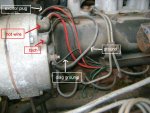
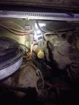
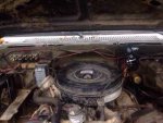
I'm new to CUCV's. I bought one from a friend. The owner before him converted to 12v. He did the Rosco. conversion. I've had a huge problem with the truck starting and the batteries constantly dying. There are no draws that I can tell. So I'm going back to 24v. The existing wires for the drivers side alternator is no longer there that I can find. What would be an easy and correct way to wire it up like it should be to go back to 24v. The only wires I really need help with are the wires for the drivers side alternator. I'll probably have to run all new wires. Any advice? Here is what my firewall looks like


BC54D344-2498-4D84-9BC9-E4CFD2AE4A1A.jpg
 

MarcusOReallyus

Well-known member
4,524
816
113
Location
Virginia
Well, welcome to the forum! :beer:

While I don't disagree with converting back to 24v, that's not going to solve a drain problem, assuming the Roscommon conversion was done correctly.

Here's a weird question, but there's a reason for it. Does your horn work?

Read that thread I linked and you'll see why I asked, and will have a pointer on where to look for the drain.
 

bmorrow

Member
47
0
6
Location
Ooltewah TN
Marcus: Thanks! I don't think I have a draw issue. (but I could be wrong) Yes my horn does work. How would you test whether or not you have a drain? I know how to on a normal single battery 12v system. As far as the Roscommon conversion goes, I think everything was done correctly. What puzzles me is why wouldn't the 12v conversion work if done right. From what I can see it's usually a pretty successful conversion but I can't keep the blazer running for nothing. (The battery dying over the course of a days time period.)

Makers: do you happen to have a picture of what the firewall looks like?

My next question is I don't have the big resistor box for the glow plug relay anymore. Should I buy an original part or is there a better way to drop it down to 12v. I think I read something about Doghead doing a bypass of some sort. Any ideas?
 
Last edited:

Warthog

Moderator
Super Moderator
Steel Soldiers Supporter
13,774
232
63
Location
OKC, OK
The alternator can cause a battery drain. To test remove the two wire plug and let it sit a couple of days to see if it drains.
 

Warthog

Moderator
Super Moderator
Steel Soldiers Supporter
13,774
232
63
Location
OKC, OK
With pictures of what you currently have we should be able to help you out.
 

MarcusOReallyus

Well-known member
4,524
816
113
Location
Virginia
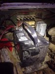
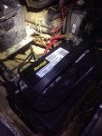
The starting system, so we can verify that the conversion was done properly.

When I mentioned a drain, it was because you said that the batteries were constantly dying. The thread I linked describes one possible reason for that, Warthog mentioned another. The diodes in the alternator can go bad and drain your batteries. If you charge them up, disconnect the alternators, and wait a few days, the batteries should still be charged. If they are connected, and the batteries go flat, you know it's time to rebuild or replace your alternators.

Rebuilding is easy. ASP Wholesale has the parts at a good price.
 

bmorrow

Member
47
0
6
Location
Ooltewah TN
Oh ok. I see. I actually just replaced the passenger side alternator a few days ago and the batteries will hold a charge forever if it's just sitting but they die when it's actually running.
 

bmorrow

Member
47
0
6
Location
Ooltewah TN
Anybody have advice? I'm in the middle of using some of the charging system diagrams people have posted on here to help me go back to 24v system. What I've learned is my wires are moved quite a bit. My next question is, how do i go about re-installing the nonexistent glow plug ballast resistor. I'm seeing that the resistor is not necessary if you bypass something. What mod is this exactly?
 

bmorrow

Member
47
0
6
Location
Ooltewah TN
So how would I go about doing that? Run a hot wire from the front battery straight to the GP relay? Im a newb to wiring, especially these 24v systems.
 

bmorrow

Member
47
0
6
Location
Ooltewah TN
I plan on doing your resistor bypass method. What is that yellow looking thing you circled in the second picture?

Also, where does that blue/ red wire with that yellow looking thing go to? I can't follow the wire very easily. Thanks
 
Last edited:

nyvram

New member
115
1
0
Location
Franklin/TN
Hope you found mine. Make sure you fuse that thing. :beer:
Not to hijack, but read your thread (very interesting) and I'm curious if you happen to have the exact lengths of cables, fuse, etc. you ordered so someone could repeat your project in its entirety.

Did you ever rework the ziptied cable from the fuse to the battery?

I read the GP resistor bypass in the FAQ and your thread..but I'm not 100% sure I get the benefit here.

Is it to eliminate the complexity associated with the resistors converting 24v to 12v for the glow plugs and simply provide 12v to the GP directly and eliminating a potential failure point?
 

MarcusOReallyus

Well-known member
4,524
816
113
Location
Virginia
I plan on doing your resistor bypass method. What is that yellow looking thing you circled in the second picture?

That's a bad connector that I circled. See how it's burnt?


Also, where does that blue/ red wire with that yellow looking thing go to? I can't follow the wire very easily. Thanks
If you mean the wire that's attached to the yellow thing I circled, that's the original feed to the terminal block. That's the power source for pretty much all the 12v in the vehicle. It goes back to the battery.
 

MarcusOReallyus

Well-known member
4,524
816
113
Location
Virginia
Not to hijack, but read your thread (very interesting) and I'm curious if you happen to have the exact lengths of cables, fuse, etc. you ordered so someone could repeat your project in its entirety.

Two pieces of wire:

1 ea. 6' x 6 AWG Battery Cable Tinned Marine Grade Wire Red
1 ea. 18" x 4 AWG Battery Cable Tinned Marine Grade Wire Red (I would make this 24" instead)
Plus connectors.

The total order came to $24.68.

I ordered the cables from http://www.bestboatwire.com/

The fuse & fuse block came from Amazon. The brand is.... not sure. One of the better marine brands. Electrical stuff is not a place to go cheap.


Did you ever rework the ziptied cable from the fuse to the battery?
Not yet. The truck hasn't moved! I've been chasing some other electrical gremlins and alternator problems and super busy. It's not my DD, and my DD has had problems, I've replaced a transmission on the wife's van, etc. etc. etc. Oh, plus getting in the firewood for the winter, etc. etc. :mrgreen:

I plan to replace that 18" section. I'm going to re-route it to the front battery, and I need a few more inches. I'll encase it in corrugated loom where I plan to attach it to the battery holder.


I read the GP resistor bypass in the FAQ and your thread..but I'm not 100% sure I get the benefit here.

Is it to eliminate the complexity associated with the resistors converting 24v to 12v for the glow plugs and simply provide 12v to the GP directly and eliminating a potential failure point?
Not exactly. The stock system is what we call a "voltage divider circuit". When current flows along a path which has resistors in series, the voltage drops across each resister. How much it drops depends on the ratio of the resistors. For example:
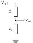
simple voltage divider circuit.png

If the resistors are of equal value, the voltage at V-out will be 1/2 of the voltage at V-in. However, if the resistance at Z2 is higher than Z1, the voltage at V-out will be higher.

Well, it turns out that when we have resistors in parallel, the value of the total is LESS than the value of just one of those resistors. for example, if we have 10 resistors in parallel, and each one is a 10 ohm resistor, the total resistance will be 1 ohm. (That makes sense - there are more paths for the current to take simultaneously. It's like having more holes in a tank - more fluid will flow.)

That's what we have with our GP circuit. Each GP has a certain resistance, and together they present a lower resistance to the current than just one.

But take one GP out of the circuit (by burning it out), and now the total resistance is higher than before (like plugging one of those holes in the tank). Whoops! What just happened to our voltage? It just got higher. What does that do to our GPs? They are getting more voltage, and therefore more current. They will age faster, and they will burn out sooner. What happens when the next one goes? Right, the total resistance is now higher, and the voltage is higher, speeding the demise of the remaining GPs. Then the next one, and the next one. Each failure creates a higher voltage for the remaining GPs, which makes them burn out faster. Bang, bang, bang, bang. One after the other. This is why it's called a "cascade failure".

Take the voltage divider (the firewall resistor) out of the picture, and now all the GPs will ever see is 12v, no matter how many fail.


If you replace your GPs every time one fails, you'll never see this cascade failure, of course.
 
Last edited:
Top
AdBlock Detected

We get it, advertisements are annoying!

Sure, ad-blocking software does a great job at blocking ads, but it also blocks useful features of our website like our supporting vendors. Their ads help keep Steel Soldiers going. Please consider disabling your ad blockers for the site. Thanks!

I've Disabled AdBlock
No Thanks