• Steel Soldiers now has a few new forums, read more about it at: New Munitions Forums!

  • Microsoft MSN, Live, Hotmail, Outlook email users may not be receiving emails. We are working to resolve this issue. Please add support@steelsoldiers.com to your trusted contacts.

H-1 Ground Support Heater, NSN 4520-01-056-4269

Wire Fox

Well-known member
1,252
161
63
Location
Indianapolis, Indiana
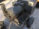
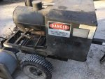
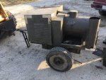
I just brought home an older ground support heater, NSN 4520-01-056-4269, manufactured by Davey Compressor Company of Cincinnati, Ohio. It's definitely a bit rough around the edges, but it looks like all of the essential equipment is there and in-tact. The hour meter reads out about 1400 hours, so it seems that it was rather well-loved in its day. Also a nice perk is that when the seller got it, there was a twin also being discarded where the other recipient only really wanted the trailer, so he took most of the other equipment off of it-leaving me with a spare control panel (including the regulators mounted to the under side of it), spare diesel engine, and spare blower assembly. Not a bad deal for all of this at less than the price of single small engine!

I can't find the exact manual for this unit, but have found similar ones that will definitely be helpful on their own; however, if anyone has this manual/T.O., I'd really appreciate it. It should be T.O. 35E7-2-11-11.

This unit appears to use a single shaft-driven fuel pump & fuel filter for both the engine and combustion chamber (if I read it correctly, some similar models seem to indicate having a separate v-belt driven pump for the combuster). Another thing that seems to be different is the trailer chassis and speed rating: most look like they have a sort of of U or O-shape chassis, but this is a more traditional ladder frame. As well, the wheels are pretty typical to the average small trailer I've seen, the "tow bar" is a nice, full-length trailer tongue that doesn't fold or slide, and there's marking on the trailer indicating a top speed of 50 MPH-much better than the 20 MPH most trailer-mounted H-1 heaters are rated for! As for obvious defects, I've already encountered several cracked O-rings. Without a manual, I know I'm going to need to learn to measure o-rings correctly and pay a visit to my local supply house to replace these one-by-one. As well, to be expected, the fuel is positively bad that's sitting in the tank. I need to drain it all out, clean the tank, try to purge the lines, and change the fuel filter prior to trying to start this.

Oh, and this heater also already helped educate me on what an "oil bath filter" is. I went to check the air filter, expecting to have a dry element or a lightly-oiled foam filter, but then had the bottom drop out and spill oil all over my leg and the floor...oops. After doing some googling to see an example of that filter and realizing that it was meant to be that way-not some odd backflow of oil into the air filter-I accepted that I was just an idiot and proceeded to throw my pants in the washer.

Here's the data pulled from nsn-now:
MOUNTING TYPETRAILER
HEAT MEDIUM TYPEAIR
CIRCULATED AIR TYPEHEATED
WIDTH55.000 INCHES NOMINAL
CURRENT TYPEDC
DEPTH70.000 INCHES NOMINAL
PRIME MOVER TYPEDIESEL ENGINE
CURRENT RATING IN AMPS35.0
HEATING ELEMENT TYPEBURNER
IGNITION METHODELECTRODE
HEAT DELIVERY RATE400000.0 BRITISH THERMAL UNIT
INTEGRAL FUEL TANK CAPACITY24.5 GALLONS
VOLTAGE IN VOLTS24.0
FUNCTIONAL DESCRIPTIONDESIGNED FOR PREHEATING AIRCRAFT ENGINES,COCKPITS AND CABINS WHERE THE AFCT OPERATE IN ARCTIC REGIONS
FUEL TYPEJP-4 JET FUEL AND JP-5 JET FUEL AND DF-A ARCTIC DIESEL FUEL OIL AND DF-1 WINTER DIESEL FUEL OIL AND DF-2 REGULAR DIESEL FUEL OIL
HEIGHT42.000 INCHES NOMINAL
REFERENCE DATA AND LITERATUREAF TO. 35E7-2-11-1
SPECIFICATION/STANDARD DATA81349-MIL-4607 GOVERNMENT SPECIFICATION
NONDEFINITIVE SPEC/STD DATA4 CLASS
UNPACKAGED UNIT WEIGHT734.00 POUNDS


Will edit soon to mobile upload some pictures... Including the seller's photos right now. Edit 4: there's my pictures I took this morning!

EDIT: This thread is the same unit as mine. The engine P/N matches up, too: https://www.steelsoldiers.com/showthread.php?28300-Heater-Trailer-Help
Another EDIT: Found a document from Hatz-Diesel that gives specs like oil type, volume, temperature ranges, torque specs, and tolerances for the various engines. Assuming I'm interpreting the P/N correctly, this would be a variant of their E-673 engine, which has a full set of specs in the attached PDF.
Edit 3: Found a parts manual that helps my case on the P/N format (LN is a sub-option), plus I also found a repair manual the covers the E-571, 671, 572, 672, 573, and 673 models. I've got the part manual uploaded, but the repair manual won't go through for some reason. I'd be happy to email this to a MOD if they can add upload it for me...
 

Attachments

Last edited:

Wire Fox

Well-known member
1,252
161
63
Location
Indianapolis, Indiana
Alright, so I've gotten a start on getting truly hands on. Drained and rinsed the tank with some fresh fuel, changed the engine oil (well, it had no oil. I just ended up filling it), and attempted to change the fuel filter unsuccessfully (more on that soon...). Slaving off of my HMMWV and following the operating instructions on the data plate, I got it to fire right up! The engine roared up to life pretty quick and seemed to be going well, but started surging and eventually would slow and die. I could immediately restart, but it would slow and die faster, the less it sit.

I popped off a fuel return line to see how much girl was getting back and it was a pretty substantial volume. I filled a pint container in under a minute, stopping with the engine starving and dying. With that much fuel on the return from the engine's injection pump, it doesn't seem like fuel pressure and volume should be the issue...

That said, I found it suspicious that the fuel filter installed is a PH51A oil filter. I've been very unsuccessful in finding a suitable replacement filter actually rated for fuel use (with water separator) that can fit in the space. The 8" filters are just barely too long... If you think that an oil filter can actually work in this role, let me know. The PH51A at least does not have a bypass. It's M18-1.5 thread size makes it harder to buy substitutes... http://productguide.luber-finer.com/Home/PartDetail?partNo=PH51A

As well, I'm trying to learn how to service those oil bath air filter. I recognize that it's entirely possible that my actual problem is this air filter being clogged, but I can't figure out how to remove and clean the packing material after I have the oil bath can removed, at least without seemingly destroying the fiber. I'll be digging around YouTube and some similar engine repair manuals trying to figure this one out. Until then, I'd appreciate some tips!

Sent from my Nokia 6.1 using Tapatalk
 

D6T

Well-known member
228
532
93
Location
Vermont
You need to join the forums at Bob Is The Oil Guy, those people will climb out of the woodwork with all of the answers you need. I’m afraid I can’t offer any help but I’m very interested to see where this goes. Thank you for sharing that with us.
 

Wire Fox

Well-known member
1,252
161
63
Location
Indianapolis, Indiana
What to do with the air filter is straight out of the Hatz Repair manual:

Remove oilbath-airfilter by unscrewing fixing nuts on airintake flange of cylinder head. Do not tip oilbath-airfilter after removing since filter oil would run into filter element. When starting the engine this oil would be sucked into the engine and cause a dangerous increase of engine speed and thus might damage the engine.

For cleaning remove oil tube by opening clips. Remove dirty oil and clean tub thoroughly with fuel. Fill clean oil up to mark "a" on the tub.

Rinse detachable filter element thoroughly with fuel. Do not reassemble filter element immediately after rinsing but allow fuel to drip out for 10 minutes. Clean air-intake apertures carefully. Also the non-detachable filter element in the oilbath-airfilter has to be cleaned from time to time by repeated dipping and rinsing of the upper part of the filter in fuel. Wait 10 minutes in order to allow fuel to drip out.

Note:
The engine life is dependent on the proper maintenance of the oilbath-airfilter, which is therefore of particular importance. A neglected oilbath-airfilter causes premature wear since unfiltered or insufficiently filtered air is sucked into the engine. An oilbath-airfilter without oil in the oil tub is absolutely useless.

The exhaust silence can be detached by unscrewing the fasting nuts and the corresponding flange on cylinder head.
In short, sounds like I need to actually pull this off the engine to get a clearer picture of how to disassemble the filter, as there should be both a removable and non-removable filter element-I'm likely hung up on the non-removable element, plus I saw that there definitely was already oil in the filter, so that needs cleaned regardless.

As to the advice on checking out bobistheoilguy, that's a great idea! I've read many discussions over there and know that they can get quite in-depth, so they've very likely to be able to help!
 

Guyfang

Moderator
Staff member
Moderator
16,676
23,820
113
Location
Burgkunstadt, Germany
This thing is Air Force equipment. I have looked everyplace I can think of, and can't find a TO for it. There has to be someplace that keeps this sort of TO. As long as it's for public release, it should be available. I will try an Air Force tech guy in Ramstein in the morning. I don't have his email, and it's 24:00 now.
 

Wire Fox

Well-known member
1,252
161
63
Location
Indianapolis, Indiana
This thing is Air Force equipment. I have looked everyplace I can think of, and can't find a TO for it. There has to be someplace that keeps this sort of TO. As long as it's for public release, it should be available. I will try an Air Force tech guy in Ramstein in the morning. I don't have his email, and it's 24:00 now.
You're the best for taking the effort to look for that, even if you end up not turning up anything.

I did find an army TM that covers another piece of equipment that uses the same engine. It's been helpful at understanding some of the operations of the engine that weren't covered in any repair manual yet. Still, none of these adequately cover diagnostics of the combustion system and proper testing values of the various electronics on it. The data plate still does show me what each testing point's fuel operating pressure should be, so that's a small relief...

Liquid fuel transfer pump:
TM 10-4320-310-14
TM 10-4320-310-24P

Sent from my Nokia 6.1 using Tapatalk
 
Last edited:

Wire Fox

Well-known member
1,252
161
63
Location
Indianapolis, Indiana
Nice! While looking for information about the fuel pump, I stumbled upon the patent for the exact heater I'm working on. Funny enough, the patent literally expired today. https://patents.google.com/patent/US4276018

The attached PDF has multiple detailed drawings and the dialog of the patent very clearly explains the operation of the heater and how one component interacts with the next. This is going to go a long with helping me trace out the problems in the unit...

In a sad twist, Suntec/Sundstrand is informing me that I'm SOL on the fuel pump, as the model on there is very obsolete and they state there's no parts (including gaskets and filters) available, plus there's no direct replacement available. I'll probably still give their current J-series parts a try, as I bet that they're more similar than they let on, plus I think my main focus will need to be on the Bosch injection pump.

EDIT: I think I may have figured this out. Reading the description in the patent, I can see that all of the fuel is going to pass through the main fuel pump (the injection pump does not do significant self-draw, like I've come to expect with larger pumps). With the heater de-engergized, all of the fuel it pulls is going to dump through the bypass line, which is pushed to the injection pump and any excess returns to the fuel tank. When it heater is energized, a solenoid opens, allowing fuel to both be pushed to the injector for the burner and to send fuel to the injection pump on the engine (plus dump any excess). In testing, I find that running for several minutes will eventually lead to the engine slowing down from apparent fuel rate loss and will stall. If I turn the burner on, the engine will almost immediately begin this process and will begin to fail rapidly. Switching it off can sometimes save it for a few moments before requiring a restart. If the system has a few moments to settle while off, it can easily start and run again for a couple of minutes without any repriming-the lack of repriming makes me think that it's not air intrusion, though this is at high risk of that due to age of the soft fuel lines. My hypothesis is that I have obstructions in the fuel pump's internal filter. As the system runs, the obstructions are picked back up and gradually jam the filter again, ultimately leading to its failure. Lack of pressure allows the worst of the sediment to fall and thus the engine can restart again. Now, this could also just be an improper main filter on my part that has too low of a fuel rate. The best that could be located expediently was a FRAM PH3980, which is supposed to be a 20 micron filter with anti-drainback and no bypass. There is no water separation capability, but the GPM is relatively low at 3 GPM for engine oil, which may be restricting the engine since diesel pumps always work with an excess of fuel.

I will inspect the fuel pump's filter for substantial contamination and clean it as best as possible due to no replacement being available and check for performance improvement. Failing that, I will source a more appropriate fuel filter that should be able to guarantee proper flow. Failing that, I will replace fuel lines. Lastly, I will inspect the fuel injection pump. If that can't get this engine to run reliably without losing power, I have no idea what will. Once the engine is running, then I can focus on getting the burner's injector and igniter system working properly-then finally on to repairing the alternator's charge system and re-calibrating the output thermometer.
 

Attachments

Last edited:

Wire Fox

Well-known member
1,252
161
63
Location
Indianapolis, Indiana
I may have one of those fuel pumps, let me do some digging.
Let me make sure I actually need one first before you dig too hard. I have a chance to turn the wrenches again tonight to check it. I also have a proper fuel filter arriving tomorrow I'm case it's not the pump.

Sent from my Nokia 6.1 using Tapatalk
 

Wire Fox

Well-known member
1,252
161
63
Location
Indianapolis, Indiana
I pulled the fuel pump assembly open...the strainer and gasket looks like the spitting image of the part they're still selling, so I bet they're still compatible. There unfortunately wasn't much to clean off the strainer and the inside of the pump also looked pretty clean. After reassembly and repriming, it seemed like it was running great...engine was stable-running for several minutes with no signs of surging or dark smoke. It even handled the burner solenoid opening just fine and didn't cause any issue to the engine...then I tried to adjust the throttle and it all came back down to its old behavior. Surging, black smoke, loss of power, and stalling. This time, I was measuring the temperatures as I was going along and I found that the head held a very steady 180F and the exhaust was around 300-350F on the surface. As soon as the surging started, temperatures rose up. The exhaust peaked over 500F and the head peaked around 220F.

Black smoke? Elevated EGT? Inconsistent RPM? Loss of power? This now instead must be between the injection pump or the injector itself from over-fueling (probably something is sticking, or the nozzle is clogged). I see a very expensive replacement injector on eBay right now, a rather cheap injector nozzle on eBay in Germany, and a few moderately priced injection pumps on eBay as well-everything in brand new condition. Obviously cleaning and repair is the best choice to save cash, but it's nice to think that I might be able to get the right parts if something is worn too far out of spec.

EDIT:. I almost forgot I took a video. Everybody likes moving pictures. Here's a 30 second clip of the engine pretending to be nice, just before I adjusted the throttle and it all went to ****.
https://youtu.be/2Sl6QKld6_U
 
Last edited:

Wire Fox

Well-known member
1,252
161
63
Location
Indianapolis, Indiana
New filter installed, but didn't make the difference (it makes me feel better having a proper fuel filter with water separator). Injector removed and it indeed had a lot of carbon build-up on it. I did some cleaning, but couldn't get the bugger disassembled. As it was, it barely came out of the engine. I locked the injector into a vice, put large wrench on the cap that hold the injector together, and wailed on the wrench for 20 minutes with a 3lb mallet and didn't get it to budge even a bit. I'm going to take a look at the injection pump before I double down on beating the injector apart. As it is, if somebody has a Hatz 40006600 / BOSCH 0432297022 injector they'd like to sell for a reasonable price, I'd happily hear you out! ...or, if anybody knows tricks for opening up old injectors, I'd like that, too.
 

Wire Fox

Well-known member
1,252
161
63
Location
Indianapolis, Indiana
Put it in a pot of atf and set it on 5he stove for an hour prior to wailing on it.
That's sounds like a trick I can believe in-and I think I've seen that before. Sounds like a stop by Goodwill for a cheap pot is in order. Good thing I already have a butane burner for outside, or my wife would murder me...

Sent from my Nokia 6.1 using Tapatalk
 

Wire Fox

Well-known member
1,252
161
63
Location
Indianapolis, Indiana
Didn't tear into the injector yet, but I did just strip off the entire blower, burner, and heat exchanger assembly to inspect and clean those. This also happens to make it remarkably easier to access and work on the engine, as I basically now have three sides with absolutely unfettered access.

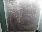
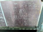
I took a couple of photos of the data plate, mostly to make it easier to sit at a computer and recheck diagrams without having to go grab that humongous steel casing to look at the data plate. They're attached here, in case anyone has one of these with an illegible data plate. As a side note, that electrical schematic sucks to read! I've never dealt with one that had all the connections overlap and just designate their endpoints out by number. A few leads are very confusing as a result...

Lastly, I've officially filed a FOIA request for TO 35E7-2-11-1. Some helpful folks have tried to find the manual for me but didn't have it available, commerical resources have rejected my request on the grounds that it's restricted, so I've now gone straight to the top to see if the USAF HQ will authorize release of the manual.IMG_20190608_202949.jpgIMG_20190608_203004.jpg

Sent from my Nokia 6.1 using Tapatalk
 
Last edited:

Guyfang

Moderator
Staff member
Moderator
16,676
23,820
113
Location
Burgkunstadt, Germany
Have you looked at Herman Nelson heaters on line? very similar to your unit.
When you use the phrase, "Herman Nelson", you have to also use the model number. For me, a "Herman Nelson is heater renowned for blowing up in your face, heater from the 50-70's time frame. Most folks know a completely different Hermon Nelson today.
 

Wire Fox

Well-known member
1,252
161
63
Location
Indianapolis, Indiana
I feel dumb on the schematic. I posted here before about the patent being out there in full text. I completely overlooked that the 10th page (Figure 14) is a traditional schematic that meshes up with what I'm interpreting in the dataplate version, but is actually reasonably easy to follow, plus everything is labeled.

I can also confirm: my unit is wired wrong. There's indeed a 12V tap between the batteries that's NOT present on my unit. I'll have to do some careful tracing to make sure that it's not anything to do with someone having modified the unit to be all 24V components (or had installed a small converter), but beyond that, it's a clear indication that the flame controller will never work until I correct the wiring (if it's not already destroyed). Another thing is the wrong switch is on my unit. The schematic clearly shows a three-position switch (start, run, off), but my unit is only a two-position (start is momentary, run is constant-you kill it by cutting fuel). Off is just no-connection, so it's not fundamentally different, but it would leave room for there to be some parasitic draw that otherwise wouldn't be possible.

EDIT: I'm looking at this schematic and trying to further understand the purpose of this part of the circuit. In the green-highlighted section, it's 12-14V coming in from the rear battery. In the orange-highlighted area, we have 24-28V coming in from the pair of batteries. When switched on, these two circuits join in parallel to form a voltage divider. I'll have to go and measure the resistor to know for-sure what's supposed to be happening here, but right now, it looks like either there's a very odd system to have 12-14V, or they need some value between 12V and 28V and this was determined to be the simplest way to get that voltage level. Anybody have any hunches?
 

Attachments

Last edited:
Top