• Steel Soldiers now has a few new forums, read more about it at: New Munitions Forums!

  • Microsoft MSN, Live, Hotmail, Outlook email users may not be receiving emails. We are working to resolve this issue. Please add support@steelsoldiers.com to your trusted contacts.

Haldex PUREst dryer failure - casting defect?

GeneralDisorder

Well-known member
Steel Soldiers Supporter
1,611
4,392
113
Location
Portland, OR
I've been fighting my air system not holding (perfect) pressure overnight since I bought this truck in '21. Even after fixing every leak I could find, the pressure would drop overnight - depending on ambient temperature - usually from full tanks to about 60 psi but at times if it was fairly cold down to 30 psi or so. Colder temps would make it leak worse. I fixed literally dozens of factory push connect air line fittings - they used plastic push connect fittings all over under the dash, etc. I completely rebuilt the PUREst dryer with every kit HALDEX has available for it including a new heating element, etc - It got better but still varied according to temp and I just could not find any leaks.

Then one day a few months ago I heard something at the dryer but no amount of soapy water would show anything - after feeling around I got the leak to change tone a bit when my hand was over the main pressure relief valve on the bottom of the unit. This guy:

PXL_20240606_173901559~2.jpg

PXL_20240409_173300160.jpg

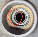
The problem is it's down in a hole (soapy water can't get down to the leak since this port is upside down on the truck) and at first I though it was the valve itself - a part that HALDEX doesn't sell 😒. Turns out it wasn't - the leak was from around the (new) o-ring that seals this valve to the housing. What I found is that the o-ring sealing surface down inside the hole is damaged or defective and even after replacing the o-ring and trying a couple different sizes and Molykote 111 it just would not seal up. Cursory inspection it all looks fine (it's a fairly deep pocket, it's small, and it's upside down):

PXL_20240410_164554440.jpg

But on CLOSE inspection the problem is revealed and the "fix" is not necessarily obvious. Could likely make a tool to recut the seat for the valve. Maybe some careful application of epoxy could allow the o-ring to seal sufficiently..... I just decided to get a new old stock surplus dryer for $450 because the reality is that it comes with a new cartridge which is about $120 anyway so $330 for a guaranteed fix was worth it to me to (potentially at that point) fix my years of frustration with my truck not holding air.
PXL_20240410_164617972~2.jpg

PXL_20240606_195450134.jpg

And the next morning (14 hours later) I have over 105 psi in both tanks!

PXL_20240606_161242545.jpg

Some pressure drop is expected due to the air tanks cooling off overnight from operating temp and it's not necessarily at exactly 125 when shut down since the brakes get used to stop and apply the parking brake but it doesn't take enough to load the compressor and top itself off before shut down.
 
Last edited:

Ronmar

Well-known member
3,405
6,829
113
Location
Port angeles wa
Hmmm isn’t there an outlet check valve? I am thinking that this thing should go to at atmospheric pressure every time the governor unloads and commands the purge. if it is shut down while the compressor is online the only pressure that should be able to leak away is the air in the dryer case and line back to the compressor. The outlet check should isolate it from wet tank air just as the inlet checks on the service tanks should isolate them from each other and the wet tank…
 

GeneralDisorder

Well-known member
Steel Soldiers Supporter
1,611
4,392
113
Location
Portland, OR
Hmmm isn’t there an outlet check valve? I am thinking that this thing should go to at atmospheric pressure every time the governor unloads and commands the purge. if it is shut down while the compressor is online the only pressure that should be able to leak away is the air in the dryer case and line back to the compressor. The outlet check should isolate it from wet tank air just as the inlet checks on the service tanks should isolate them from each other and the wet tank…
That's what I thought too. But this dryer has TWO relief valves. One that was originally 150 psi (Haldex later changed this to 175) that is the safety relief valve for the discharge check valve, and this unit which is a 250 psi relief valve. I'm thinking this 250 psi valve is on the purge signal port from the governor. The governor has tank pressure on it all the time and when it unloads there is tank pressure on the unloaders and also on the dryer purge port. Also you can't buy this relief valve - it has no part number call out on the parts breakdown. I can't find a diagram of how the dryer is plumbed internally but I can't see what other use it would serve and every explanation I can find of dryer operation does not include a second relief valve so......... 🤷‍♂️

PXL_20240606_173901559~2.jpg

I will pull the old dryer housing out and figure out where the relief valve is plumbed to. Not immediately at hand at the moment.

All the system check valves are new at both brake tanks and of course the new dryer and the old dryer both had/have new outlet check valves. I changed it multiple times on the old dryer with no effect.

New dryer works perfectly and system holds pressure now. Governor is new as is the compressor cylinder head (rebuilt and swapped that out a couple weeks ago due to bad unloader piston o-rings).
 
Last edited:

Ronmar

Well-known member
3,405
6,829
113
Location
Port angeles wa
Well the governor only has wet tank air at its disposal to feed the purge valve. At worst this would leak away that air, but any loss of service air is happening elsewhere…
 

aw113sgte

Well-known member
Steel Soldiers Supporter
493
735
93
Location
La Crosse, WI
Where were the areas you found the leaks prior to this one? I've started the process and so far the only one I've found after spraying tons of fittings was the CTIS pressure switch. Have not done under the dash or the rear brake components yet.
 

GeneralDisorder

Well-known member
Steel Soldiers Supporter
1,611
4,392
113
Location
Portland, OR
Well the governor only has wet tank air at its disposal to feed the purge valve. At worst this would leak away that air, but any loss of service air is happening elsewhere…
I'm wondering if the service air tank check valves are leaking back to the wet tank - just very slowly and more-so when cold. I did replace them....... I do agree that in theory if the check valves are perfect the service tanks should stay up but prior to swapping the dryer they would always drop and generally by the same amount as well - which I found odd. Is there some mechanism I'm not seeing that would make the front and rear tanks equalize to each other as one loses air? :unsure:
 

GeneralDisorder

Well-known member
Steel Soldiers Supporter
1,611
4,392
113
Location
Portland, OR
Where were the areas you found the leaks prior to this one? I've started the process and so far the only one I've found after spraying tons of fittings was the CTIS pressure switch. Have not done under the dash or the rear brake components yet.
Mostly under the dash on my truck. Both sides. Also found some push-lock fittings on the back of the air-hydraulic control panel.
 

Reworked LMTV

Expedition Campers Limited, LLC
Supporting Vendor
1,494
1,166
113
Location
TN
Hard to see exactly what this is. Maybe a well placed dremel tool could clean up matting surfaces?
 

Ronmar

Well-known member
3,405
6,829
113
Location
Port angeles wa
them both leaking down equally is a good clue. The primary and secondary air are tied together in 3 other places.

1. Under the drivers dash. There is a two way check valve there that samples either system to provide park and trailer control air.
2. Inboard of the service tanks there is a 2way that samples these two systems to feed the hydraulic manifold/air operated hydraulic pump Via a park air controlled valve.
3. Rear crossmember brake component location(port side), there is a 2way check that samples both service tanks to feed the anti-compound relay valve which uses it to provide the air that actually releases the park brakes/compress park springs

and of course the two systems come together in the treadle valve. They are supposedly separate valves but a interconnecting linkage issue might cause both systems to vent out that hard to access exhaust port up in front of the radiator, same with a park control valve leaking past… my park control also used to leak past its spindle/handle, and it was worse when it was cold(could actually hear it when cold)…

IMG_3892.jpeg
 

Ronmar

Well-known member
3,405
6,829
113
Location
Port angeles wa
Wow in looking at this, i reviewed my brake component video and I just found another, what looks like from the factory, problem with my brake plumbing… Because the anti-compounding valve is not fed from the correct source, i don’t have any emergency braking capability. I wonder, if like the wet tank plumbing error, this applies to only A0 trucks?
 

GeneralDisorder

Well-known member
Steel Soldiers Supporter
1,611
4,392
113
Location
Portland, OR
I just pulled this up to look at - posting it here before I try to read this myself o_O

2039E2_large.jpg

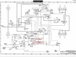
I compressed the image file and attached it so the forum wouldn't resize the image to unreadable. This should be the A1+ pneumatic system schematic.
 

Attachments

Ronmar

Well-known member
3,405
6,829
113
Location
Port angeles wa
Well that drawing has some issues. Did they do away with the load proportioner On the A1?

that low pressure warning switch in the middle of the drawing is actually what controls the park and emer lights in the dash(plumbed to park circuit).

They have the dryer output bypassing the wet tank. That is contrary to any air system diagram or system i have played with, except the A0. My A0 was plumbed like your A1 drawing(wet tank Td off the dryer output), but the A0 drawing i attached above shows it like I believe it should be with 100% of the air passing THRU the wet tank.
every A1 truck I have seen or had people confirm the plumbing on, is plumbed like the A0 drawing(correctly) with 100% of the dryer passing thru the wet tank to reach the primary tanks. And every A0 I have looked at or had people check is plumbed like this A1 drawing(wrong imo)…

i suspect that if you look at yours you will find the dryer output plumbed THRU the wet tank…

now in modern systems they have started doing away with the wet tank because the dryers are supposed to be so much better, but having see the results of a failed dryer cartridge first hand, I think I would still want a wet tank inline to try and catch the debris…:)
 

GeneralDisorder

Well-known member
Steel Soldiers Supporter
1,611
4,392
113
Location
Portland, OR
I'm going to check the newest sources I have for other diagrams. Yes they did delete the load proportioning valve - not present on my truck.
 
Last edited:

GeneralDisorder

Well-known member
Steel Soldiers Supporter
1,611
4,392
113
Location
Portland, OR
Well that is the newest diagram I can find. Indeed the dryer discharge is not T'd off to the tanks. It goes through the wet tank and the only thing T'd to that is a 3/8" line..... I guess that's "TO DRESSED ENGINE" - whatever that means. That line is in the bundle of lines going toward the front of the truck.

I see the two-way valve at the back for the anti-compounding valve (#3 in your list). And I think for #1 - isn't that under the cab on the inside of the step curtain? All of the one way and two way valves on the step curtain are new. As is the parking brake control (mine also leaked from the handle stem).

I don't know where #2 in your list would be. I don't see anything near the service tanks and the line from the hydraulic control panel - I can see it crossing from the right side of the truck to the tank side, but I'm not sure exactly where it's headed. My control panel is pretty simple with no cab air ride and I've soaped down all two of the connections and the momentary push valve to operate the pump and can't find any leaks there (although it's not cold and nothing seems to be leaking at the moment). The truck wasn't driven yesterday and had over 90 psi in the tanks this morning.

1000004860.jpg
 

GeneralDisorder

Well-known member
Steel Soldiers Supporter
1,611
4,392
113
Location
Portland, OR
The line from the hydraulic control panel is coming from the back of the truck. Looks like it's coming from a 2 way check valve off the side of the inversion valve? One port on the three way (?) is T'd into the park valve air line coming into the inversion valve.....

1000004864.jpg

1000004862.jpg
 

Ronmar

Well-known member
3,405
6,829
113
Location
Port angeles wa
Yea I think they did away with the park air controlled AOP supply valve in later trucks. I have seen one where the AOP supply is fed from one of the Ts on the wet tank.

the park air control supply 2way is in the cab on the forward bulkhead In the A0. not sure where it is at on the A1s.. pri and secondary air come up thru the floor into stacked T fittings(3 ports each). One leg feeds the treadle, one leg feeds the air pressure gauge sensors and the last leg from each source feeds a 2way check, the output of which feeds over to the park and trailer control.
 

GeneralDisorder

Well-known member
Steel Soldiers Supporter
1,611
4,392
113
Location
Portland, OR
Yea I think they did away with the park air controlled AOP supply valve in later trucks. I have seen one where the AOP supply is fed from one of the Ts on the wet tank.
You don't think the valve that's off the elbow of the anti-comp valve park air inlet is a three way for the AOP supply?

Or is that not park air coming into it.... damn I need to trace the line to the hydraulic panel. I'm going to disconnect it at the panel see which line it is in the back.
 
Last edited:

GeneralDisorder

Well-known member
Steel Soldiers Supporter
1,611
4,392
113
Location
Portland, OR
Ok so I did confirm that the AOP supply is coming from the two-way valve off the side of the anti-comp valve and that 2-way is indeed controlled by the park control air. So my marked up pictures above are correct. I chocked the wheels and disengaged the park diaphragms (found leaking fittings at the left rear hub that only leak when park is disengaged - :poop:).

Wouldn't this guy up behind the step curtain be the parking brake three way with the low air warning lamp switch on it's discharge port?

1000004867.jpg

1000004866.jpg

There's no three way valves under the drivers side dash. It looks like this:

1000004150.jpg
 
Top
AdBlock Detected

We get it, advertisements are annoying!

Sure, ad-blocking software does a great job at blocking ads, but it also blocks useful features of our website like our supporting vendors. Their ads help keep Steel Soldiers going. Please consider disabling your ad blockers for the site. Thanks!

I've Disabled AdBlock
No Thanks