• Steel Soldiers now has a few new forums, read more about it at: New Munitions Forums!

  • Microsoft MSN, Live, Hotmail, Outlook email users may not be receiving emails. We are working to resolve this issue. Please add support@steelsoldiers.com to your trusted contacts.

Help identifying a connector on the firewall

RotorAV8R

New member
13
0
0
Location
Spokane/WA
Hello everyone!! I have a 69 M35A2. I've been having intermittent starting issues and have located the issue. When I turn on the power switch the low air alarm will not even sound until I wiggle the connector. Then it will power up and fire up. One wire appears to be working loose.

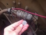
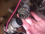
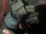
There is a LARGE connector under the hood. It's on the driver side right above the steering shaft. It has 4 pins but appears to only have 2 wires running to it. What I'm wondering is if within one of the wires there might be another cable inside that I cannot see. Is there truly only 2 wires running to this?

I'm considering cutting out the connector and just splicing the wires together making a good solid connection. Does anyone know of a reason not to do this? Should I try to find this huge connector? Does anyone know why this connector is here instead of just continuous wiring?

Pics attached and thanks for any help.
 

Attachments

rustystud

Well-known member
9,098
2,492
113
Location
Woodinville, Washington
I have never seen this connector before. The wire clamp in the first picture (just to the left of the connector) is not a military wire clamp. Neither is the wire clamp in the last picture. So I'm thinking this was done after this truck left military service.
 

RotorAV8R

New member
13
0
0
Location
Spokane/WA
I'd have to check but think these run to/from the starter and main power switch if it helps. The connector is the same style as others on the truck just larger.
 

NDT

Well-known member
Steel Soldiers Supporter
10,210
5,995
113
Location
Camp Wood/LC, TX
That connector used to connect to the 25 amp generator regulator. At one point, a 60 amp alternator was installed and a conversion harness was installed, that is what your defective connector is mated with. How you repair it is really up to you.
 

NDT

Well-known member
Steel Soldiers Supporter
10,210
5,995
113
Location
Camp Wood/LC, TX
A little back story on that connector. When the M35 first came out in 1950, they were equipped with an ammeter in the instrument cluster, not a voltmeter. The ammeter used a shunt, which was located inside the 25 amp voltage regulator. On the connector, one pin goes to the batteries, the other to the vehicle electrical load. The unused pins were for the two wires that at one time went from the shunt to the inst cluster ammeter. Years later, the ammeters were MWO'd out, but the shunt inside the regulator remained. The alternator conversion harness has the pins that come from the battery and lead to the vehicle loads interconnected.
 

RotorAV8R

New member
13
0
0
Location
Spokane/WA
Do you think I can just solder it into the plug?? There is some sort of high temp plastic in there but I doubt its very high temp. I've done a lot of pipe sweating and used to solder lots of circuits as an Electronics Engineer, but soldering this seems like it could be an issue. I think if I get it hot enough to solder and bond well it will melt the plastic.

Has anyone done this? Does anyone know of a new plug that I can buy?

A lot of that would make sense because I have the alternator conversion done to this one.
 

Kaiser67M715

Member
699
26
18
Location
NH
You pull the plug apart, the rear half of the connector should unscrew from the front. when you get it open slide the rubber bushing up the length of wire, trim the wire-leaving enough in the solder cups to grab with pliers. use your solder iron and pliers, remove the leftover scrap-a desolder braid works great for getting rid of the rest of the solder.

then to solder the new wire in,(sandpaper it if it has oxide covering) twist some solder together put it in the cup and trim it so the solder is just barely above the top of the cup. this will allow you to heat the cup and melt the solder, while pushing the new wire in

NOTE: check the length of trimmed wire, you only want a 1/16 inch or so of bare wire above the cup, any more and you may end up breaking the strands and repeating the process down the road

I wish I had taken pics when I had doje my wiring harness, pics are so much better then trying to talk your way through something
 
Last edited:
Top