• Steel Soldiers now has a few new forums, read more about it at: New Munitions Forums!

  • Microsoft MSN, Live, Hotmail, Outlook email users may not be receiving emails. We are working to resolve this issue. Please add support@steelsoldiers.com to your trusted contacts.

Help installing alternators m1009

toomuchjosh

New member
19
0
0
Location
Texas
Hi, I've been lurking on this forum ever since I bought a 1985 M1009 that the Grand Saline TX PD used for an unknown amount of time. All I know is that in 2007ish they parked the vehicle. About 4 months ago a private individual bought the vehicle from the police department. Shortly after, he ended up with a divorce on his hand and sold me the M1009 for quick $. It had both alternators missing and had many of the wires to the alternators cut.:evil: It was also missing batteries so I installed 2 Autozone Duralast Gold 800 CCA batteries in series and to my surprise the vehicle started right up.:shock: 
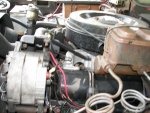
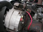
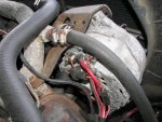
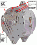
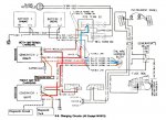
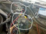
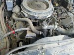
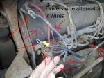
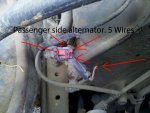
I drove around a bit but didn't push my luck. I have 1 alternator from an M1028 that I got off of eBay. Another one on the way straight from a M1009. I don't know how to hookup the wires to the alternators. I would appreciate any insight or help anyone can give me. I am uploading 4 pics with arrows to help designate the wires that need identification.

Lastly, I would appreciative any advice on items to check/change since the vehicle has been sitting for 4+ years. (I already changed the engine oil/filter, ordered fuel filters, replaced rear drive shaft u joint)
 

Attachments

Last edited:

toomuchjosh

New member
19
0
0
Location
Texas
I realized that this might be a better location for it and deleted my other/duplicate post just after re-posting it here. Wasn't trying to cross-post.
 

doghead

4 Star General /Moderator
Staff member
Super Moderator
Steel Soldiers Supporter
26,247
1,172
113
Location
NY
Schematics can be found in the back of the -20 and -34 Tech Manuals.

Do you have the TMs saved on your computer?
 

doghead

4 Star General /Moderator
Staff member
Super Moderator
Steel Soldiers Supporter
26,247
1,172
113
Location
NY
I realized that this might be a better location for it and deleted my other/duplicate post just after re-posting it here. Wasn't trying to cross-post.

I noticed that as soon as I posted. I deleted my comment. Thanks
 

toomuchjosh

New member
19
0
0
Location
Texas
I have them saved on my computer. Didn't realize they had the schematics located in the back. That is helpful, but a little beyond me. I will post back if I'm still at an impasse in a few days. Thanks for the heads up!

I'm really just trying to get this vehicle running before I leave for BCT in Aug.:razz:
 

Warthog

Moderator
Super Moderator
Steel Soldiers Supporter
13,774
224
63
Location
OKC, OK
Read the first few pages of the Trobleshooting Section of the TM 9-2320-289-20 Technical Manual. It covers how to read the wiring diagrams and what all the symbols mean.

Here are the wires for both alternators

Drivers side:

1. Large RED - 8 gauge - Hot wire on Positive Terminal - Attached to 12v terminal Block on firewall

2. Large BLACK - 8 gauge - Ground wire on Isolated Ground Post - Attached to engine Block

3. Medium RED - 16 gauge - Hotwire for excitor Circuit - Attached to 12v Positive Terminal Block on firewall

4. Medium BROWN - 16 gauge - Hotwire for Excitor Circuit - Attached to the GEN1 bulb

5. Small BROWN - 18 gauge - Feed wire for the Tach on the Diagnostic System - Attached to the STE/ICE plug under the dash

6. Small BLACK w/WHITE stripe - Ground Feed for the diagnostic system - Attached to the STE/ICE plug under the dash

Passenger Side:

1. Large RED - 8 Gauge - Hot wire on Positive Terminal - Attached to the 24v Positive Terminal Block behind the rear battery

2. Large RED w/WHITE stripe - This is the "isolated Ground" wire. It feeds 12v from the 12v terminal block to the "isolated ground" terminal on the second alternator. Make sure you have the correct wire. Sometimes the white stripe will rub off - Attached to the 12v terminal block on the firewall.

3. Medium RED - 16 gauge - Hotwire for excitor Circuit - Attached to 24v Positive Terminal Block behind the rear battery

4. Medium BROWN - 16 gauge - Hotwire for Excitor Circuit - Attached to the GEN2 bulb

5. Small orange fusable link - 20 gauge - feed wire for diagnostic system - attached to the STE/ICE plug under the dash

6. Small Black wire with a Capacitor - Some trucks still have this capacitor, some don't - Not need unless you are running Military Radios.
 

Attachments

Last edited:

Warthog

Moderator
Super Moderator
Steel Soldiers Supporter
13,774
224
63
Location
OKC, OK
Welcome to SteelSoldiers.

Make sure you visit the Cucv Wiki - Steel Soldiers::Military Vehicles Supersite (CUCV Wiki) that is at the top of the page on the CUCV Forum. All of the CUCV Technical Manuals are listed and many other helpful bits of information.

You need to download the repair manuals. You can get then for free. A couple of our members have posted them on their websites.

www.jatonkam35s.com
www.liberatedmanuals.com

The wiring diagrams are in the appendix of the -20 and -34 manuals.
Also checkout the CUCV stickys. It is where we try to post helpful tips and tricks.

Almost every question you will have has been asked and answered many times. The advanced search will become your best friend. Please don't hesitate to ask something that you can't find.

Read the TM 9-2320-289-10 Operators Manual to find out how a stock system should work. It is simular to the Operators Manual for Civilian vehicles. It tells you where all the lighs, switches, etc are located and what they do.

Three of the most important tools you can buy are:
Digital Voltmeter and know how to use it - ~$10 and up
12v Battery Charger - ~$50 for a decent one
Battery Load Tester - ~$30 for an okay one at Harbor Freight

Warthog
 

combatmech

Active member
1,213
5
38
Location
Carrollton, Texas
If you havnt already done so, ensure that you have disconnected your batteries. I have seen a few threads here where folks touched hot wires to various parts in the engine compartment with horrible results.
Best of luck!! :beer:
 

Warthog

Moderator
Super Moderator
Steel Soldiers Supporter
13,774
224
63
Location
OKC, OK
Warthog, are you talking about my post?
Sorry for not being clear. I was referring to the original poster. His first picture was labeled wrong (he has deleted it).

The pictures you posted are some I took a couple of years ago. Thanks for keeping them and using them. That is what this site is about.
 

toomuchjosh

New member
19
0
0
Location
Texas
Thanks to everyone who posted pictures and descriptions, all the info in this thread helped me out quite a bit today. I got the driver's side alternator hooked up and all the wires for both alternators ready with new connectors. Didn't realize how long it would take until the sun set and I realized I'd been outside working for 4 hours hahaha. Was 107 today in the shade aua

I connected all the 6 wires labeled for the driver's side alternator today, but, as shown in the picture I posted, I actually have 7 wires on the driver's side. The "extra" wire is a heavy gauge black wire. I will post pictures tomorrow to help with identification. I would appreciate any help figuring out what this wire is for.

@Warthog, thanks for the itemized description of each wire, that helped quite a bit today. Also, I took down the picture of the alternator that was mislabeled. as requested.

@combatmech, LOL I was messing with the wires yesterday and heard some sparking, LOL I jumped and realized exactly what your talking about. I disconnected the batteries before starting today :D
 

Warthog

Moderator
Super Moderator
Steel Soldiers Supporter
13,774
224
63
Location
OKC, OK
You will need to trace the "extra" black wire. It is not stock.

Glad we could help out. Keep us posted on your progress. I have purchased a few trucks where the wires have been cut I guess it is easier that removing the nuts when they remove the alternators
 

toomuchjosh

New member
19
0
0
Location
Texas
The unknown "extra" black wire goes into terminal 2 in the pic.

The large red 8 guage hot wire for the driver's side alt is currently going into the terminal 1 in the pic, I wanted to double check with ya'll to make sure this was correct.

Just got my other Alternator in the mail, time to get this engine running... :grin:
 

Attachments

Warthog

Moderator
Super Moderator
Steel Soldiers Supporter
13,774
224
63
Location
OKC, OK
I see a bunch of wiring problems on the picture.

First question is do you want to return it to stock?

Leave the black wire unhooked for now. It is feeding the glowplug relay. You will not have operational glowplugs, but the wiring must be fixed first before you burn something else up.
 
Last edited:

toomuchjosh

New member
19
0
0
Location
Texas
UPDATE

1, This evening I installed the passenger alternator. Both alternators are now installed and connected.

2, Both GEN lights come on now when the key is in the on position. When I push the key over to start, the GEN 2 light stays on, but is dim. Once the engine starts, the GEN1 light goes out. The GEN 2 light stays on. I re-seated the exciter plug on the passenger alt, but that had no effect.

3, the Voltmeter is not showing anything.

4, I removed the "extra" black wire from the system, but I am holding on to it just in case I need it later.

Tomorrow morning I plan to disconnect the passenger alt and test the GEN 2 light as per instructions in TM9-2320-289-20. If I need to, I can take the alternator up to Autozone and have it tested.

@Warthog, I just want the system to work reliably as possible. I understand the 24volt system works very well, when working. I am open to all options.


Sidenote, I replaced the fuel filter and that got me a bit nervous because the engine would no longer start. I realized I needed to bleed the system of air and now it starts and runs fine.

Again, let me express my appreciation to everyone that has helped me and whoever else might benefit from this tread. Thank YOU!
 

Warthog

Moderator
Super Moderator
Steel Soldiers Supporter
13,774
224
63
Location
OKC, OK
Okay, let's see what is wrong with the wiring and how bad they hacked it up.

I'll need pictures of the engine wiring and any areas that have been "taped" up. I see a bunch of tape in the picture. Also any wires that have been cut, melted, etc.

You can PM the pictures to me.

Have you checked the fuse box fuses? The very bottom fuse controlls the GEN2 and Voltmeter. Send a picture of the box.

Possibly some one modified the truck to attempt to run 12v.

It will take a little while but I think we should be able to figure it out.

What part of Texas are you from? There are alot of CUCV owners in the state.
 

Larch

Member
85
1
8
Location
US-NY
As far as your volt meter goes there is a resistor on the back, it looks like a rectangle between 2 of the posts, it is a 300 ohm resistor and they sometimes go bad. You can check it with a ohm meter, with the truck off, take your ohm meter( set it on the ohm range) and touch the two posts with the meter leads at the same time. You should get a 300 reading. If you get nothing your resistor is shot. Some have gone to radio shack and got a 300 ohm resistor and connected it to the two posts that the old one is connected to to make it work. You can leave the old one on it dosn't hurt anything. good luck.
 
Top
AdBlock Detected

We get it, advertisements are annoying!

Sure, ad-blocking software does a great job at blocking ads, but it also blocks useful features of our website like our supporting vendors. Their ads help keep Steel Soldiers going. Please consider disabling your ad blockers for the site. Thanks!

I've Disabled AdBlock
No Thanks