• Steel Soldiers now has a few new forums, read more about it at: New Munitions Forums!

  • Microsoft MSN, Live, Hotmail, Outlook email users may not be receiving emails. We are working to resolve this issue. Please add support@steelsoldiers.com to your trusted contacts.

Help with M211 series TMs

Recovry4x4

LLM/Member 785
Super Moderator
Steel Soldiers Supporter
34,012
1,808
113
Location
GA Mountains
So, I feel like an idiot asking this but my eyes hurt from looking. I have an M51A2 dump truck. It's from the M39 / G744 series of trucks that use the 211 series of TMs. Coming from the deuce TMs I know that there is a series of schematics for the electrical and air systems in an appendix in the back of TM 9-2320-361-20. I've scoured the 211 series of manuals and I can find no such collection. Am I blind here?
 

Recovry4x4

LLM/Member 785
Super Moderator
Steel Soldiers Supporter
34,012
1,808
113
Location
GA Mountains
In TM 9-2320-211-20-2-2 Chapter 28 has a few quasi schematics. It also says this;
28-1. GENERAL. This chapter gives the diagrams you need when doing troubleshooting
procedures in chapter 26. Table 3-1 is a complete listing of all support
diagrams used in this manual.


I an searching diligently for this mystical Table 3-1 and I'm not seeing it. Still digging!
 

gringeltaube

Staff Member
Super Moderator
Moderator
Steel Soldiers Supporter
6,986
2,522
113
Location
Montevideo/Uruguay
TM 9-2320-211-20-2-2 from Dec 1980, Fig. 28-1 and 28-2. That's all the electrical schematics I could find.
And for the air system, there is one full diagram shown in Fig. 48-2, followed by the system for the trailer brakes.

But you prob found all that, already?
 

Recovry4x4

LLM/Member 785
Super Moderator
Steel Soldiers Supporter
34,012
1,808
113
Location
GA Mountains
TM 9-2320-211-20-2-2 from Dec 1980, Fig. 28-1 and 28-2. That's all the electrical schematics I could find.
And for the air system, there is one full diagram shown in Fig. 48-2, followed by the system for the trailer brakes.

But you prob found all that, already?
Thank you Gerhard. I guess I'm not going crazy. I am looking to obtain a 1973 version of TM 9-2320-211-20. I'm not sure what this gem holds but maybe, just maybe, it will hold those super nice fold out schematics that the 361-20 deuce manuals have in appendix E.
 

m1010plowboy

Well-known member
Steel Soldiers Supporter
3,912
2,723
83
Location
Edmonton, Canada
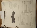
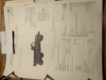
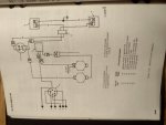
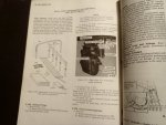
I thought I'd find a fold out in the pile of books but I'm just finding bits and pieces. Is there a specific section of a diagram you're looking for in case I stumble on it?

P1050551.JPGP1050552.JPGP1050553.JPG
 

Attachments

m1010plowboy

Well-known member
Steel Soldiers Supporter
3,912
2,723
83
Location
Edmonton, Canada
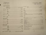
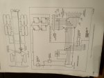
Looks like we built a Canadian version and it isn't any better. I did find a transport document for the M51a2 so if you want to take it flying, now we can.

Here are a few more snaps.

P1050555.JPGP1050556.JPGP1050559.JPG
 

Recovry4x4

LLM/Member 785
Super Moderator
Steel Soldiers Supporter
34,012
1,808
113
Location
GA Mountains
I would love to find one of the large fold out readable schematics of the chassis wiring. I did such with the CUCVs, had them printed and laminated. They are very useful..
 

gringeltaube

Staff Member
Super Moderator
Moderator
Steel Soldiers Supporter
6,986
2,522
113
Location
Montevideo/Uruguay
put .....
1973 version of TM 9-2320-211-20

I don't think it will help much, since it has NOT what Kenny is looking for...

BTW, we have that book in our own library, here...

I would love to find one of the large fold out readable schematics of the chassis wiring. I did such with the CUCVs, had them printed and laminated. They are very useful..
If it doesn't exist - make one!;-)
Q: What is so different from Peter Bog's wiring schematic for the M35A2? I think we can always use that one as a base and just add- or modify what's needed, or?

Like I made my own schematic, before doing all the wiring (harnesses), starting from zero. The modifications are (to name a few): keyed ignition/power switch mod; extra running- and auxiliary lights; back-up lights; ; additional 12V circuit and related electrics for the dual fuel system; etc.

Here's my fuel selector switch, just as a sample...
Fuel selector switch.PNG
 

Recovry4x4

LLM/Member 785
Super Moderator
Steel Soldiers Supporter
34,012
1,808
113
Location
GA Mountains
Thanks Frank. I actually bought one from this guy. You have to search title and description to get it by TM. Everything he has is excellent and is usually cheapest. I've been buying TMs from him for a long time. The cheapest 1973 version I could find was $50 used. I bought one from Milman61 new for $45 and cheaper shipping. I doubt that it will have what I seek but I like comparing the different versions and years of TMs.

G. You give me much too much credit to think I can create my own schematic. I do agree that since there are no dimensions on Peter Boggs schematic that it would suffice for a multifuel 5 ton.
 

gringeltaube

Staff Member
Super Moderator
Moderator
Steel Soldiers Supporter
6,986
2,522
113
Location
Montevideo/Uruguay
G. You give me much too much credit to think I can create my own schematic.
I can help you create one... if you (and maybe others here) help me.


Just open the attached PDF file (that's Cranetruck's revision, BTW); choose the area in question and a desired size (like 150%); then click on Edit, then "Take a Snapshot".............
1609940099946.png
and select the desired area......
1609940199649.png

Then open your old MS-Paint and paste it there....
1609940599728.png

Then you can play with it as you wish; erase and draw new lines, any color; add text and remarks, symbols, etc.
Just remember to save everything to your PC, as PNG, to be able to post it here or email it to me.

After all pertinent changes are done, we can integrate that in the whole basic schematic; rename it accordingly and convert back to PDF.

Shouldn't be that difficult, I guess...
 

Attachments

Guyfang

Moderator
Staff member
Moderator
16,755
24,064
113
Location
Burgkunstadt, Germany
I can help you create one... if you (and maybe others here) help me.


Just open the attached PDF file (that's Cranetruck's revision, BTW); choose the area in question and a desired size (like 150%); then click on Edit, then "Take a Snapshot".............
View attachment 822778
and select the desired area......
View attachment 822779

Then open your old MS-paint and paste it there....
View attachment 822781

Then you can play with it as you wish; erase and draw new lines, any color; add text and remarks, symbols, etc.
Just remember to save everything to your PC, as PNG, to be able to post it here or email it to me.

After all pertinent changes are done, we can integrate that in the whole basic schematic; rename it accordingly and convert back to PDF.

Shouldn't be that difficult, I guess...
Using the Attached wire schematic, a fella could make money by simply printing it out, (enlarge it) and then taking out to the truck and start comparing wire numbers. Yes, takes a LONG while. And there are SURE to be wire tags missing. But that can be overcome with a bit of smarts/work. When a number matches, highlight it. When not, write the actual number in the schematic. You do not have to do it all at one time. Just every
time you have to fool with the truck, DO IT. When you have it done, or as done as you want it, then use the PDF tool to replace the wire numbers.

Recovery wrote: I doubt that it will have what I seek but I like comparing the different versions and years of TMs.

The easiest way to do this is to look at the latest change cover sheet. It tells you what was changed from the last TM/Change. I looked at most of the TM9-2320-211 Series TM's. Not hardly any changes between the 1973 and later TM's. So do not expect much.

Now, I am sure Recovery knows this. He is an old timer. But for other folks who may not understand the TM, here are some tips.


1. Know how may changes have been issued for the TM you want to use. If a TM has 12 changes, and yours has only 6, you might be missing info you need. So when buying a TM, or downloading, look inside the cover, (or ask) for the latest change cover sheet number. They are in order, from oldest to newest. Often the cover of a TM will have written, With change 6. All fine and good. But if someone was on the ball, they ordered the other six changes and inserted them. The only way to tell is by seeing what the last change cover sheet is.

2. If you want to know what was changed in a TM, look at the change cover sheet. It will list what pages were taken out, and more importantly, what pages inserted. Not always the same number of pages. Then turn to the pages listed as being inserted into the TM for THIS change.

3. How are you to know what was changed? There will be a dark black "Bar" located next to text, (scan #1.) that was changed. There will be a "fickle finger of fate", pointing to ANY change, (scan #2) to a schematic. And at the bottom of the page, you will see written, Change and the change number. Change 8 (for instance, bottom left scan #1)

4. If you can buy changes to a TM you have, and they are not posted in the TM, remember this. Changes HAVE to be posted in order. Often, a change, changes an earlier change. So they HAVE to go in in order. One of my young soldiers once posted 2-3 changes to a TM. I had to break it to him, the changes were for a TM that was newer then the one he posted the changes to. So I just tossed the whole thing in the trash, rather then find all 300+ pages he had tossed in the trash, and try and re-install them. Nice job for a convict, in for life.
 

Attachments

Recovry4x4

LLM/Member 785
Super Moderator
Steel Soldiers Supporter
34,012
1,808
113
Location
GA Mountains
I've tried to follow some of the change and revision sheets and they didn't add up. They seem to now. I'll have to go play with that. Thanks Sir.
 
Top