• Steel Soldiers now has a few new forums, read more about it at: New Munitions Forums!

  • Microsoft MSN, Live, Hotmail, Outlook email users may not be receiving emails. We are working to resolve this issue. Please add support@steelsoldiers.com to your trusted contacts.

HMMWV/Civ Trailer Wiring

Jon0249

Member
111
4
18
Location
Lipan, TX
Here's my situation:

New HMMWV owner with more than one trailer wired for std 12V. Same trailers are used routinely behind my F150 and other vehicles (of friends who borrow them).

I'm trying to build a solution that does not involve swapping bulbs on the trailer, so here's what I think might work - all you EE's out there tell me if it won't please.

Three primary circuits go to the trailer - which equates to the elements on the bulbs I need to energize: Parking, Left Turn and Right Turn (the brake light signal is carried on the R/L Turn circuits). These are min legal requirements for trailers in Tx.

The general concept is to use signals from each of thee three 24V circuits (via taps) to energize relays, through which 12V - provided by a DC/DC 20A converter - will be switched to my trailer receptacle. So, I tap the appropriate wires on the HMMWV and these taps will energize the relays only when they are powered - turning on parking lights, turn signals, etc. When the coils are energized, the 12V coming from the converter is switched to the trailer lights. I believe there will be plenty of room in the battery compartment to mount the relays and converter on to a board and put together a simple harness.

R/L Turn (and brake light) circuits: As these are mostly intermittent, light duty 12v mini relays (see pic) will work on each of the R/L Turn circuits. They're plentiful in my parts bins or the local wrecking yard, too. Unless these circuits are closed for extended periods of time, the 12V relays will do fine without overheating. And it's a great use of those mini relays I've been saving.
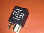
Relay.jpg

Parking: Two 12v mini relays wired in series, energized by 24v, resulting in 12v to each relay. One relay will be used for the rear parking lights and the other for side clearance lamps on the trailer, again, using 12V from the converter.

Thoughts? Anyone done this before?
 

ehinlein

Member
Steel Soldiers Supporter
65
23
8
Location
Pelham,MA
Put 12v bulbs in trailer. Use a 12v regulator on each circuit. Something like a 7805 in a to-220 package. Get a little drop but you're really at 13-14 v so will get 12 out. Put in 28v get 12 out. Just need regulators that can handle the 12v drop from the hmmwv at the amperage the bulbs require. Google voltage regulators for circuit. It's just a 3 pin component. Cheap and straight forward to use. I actually just run mine with 24v bulbs at 12v sometimes. A little dim but ok.
 

Jon0249

Member
111
4
18
Location
Lipan, TX
I did look into the 3-pin VR's, but found that the ones that were available were only good for 1A. Just looking for something a bit more robust. Thanks for the ideas.
 

Recovry4x4

LLM/Member 785
Super Moderator
Steel Soldiers Supporter
34,012
1,813
113
Location
GA Mountains
You can always put the LED composites on there. They work on both voltages. How are you adapting the 12 pin plug to the civy trailers? Many of the mil semi trailers have 2 complete lighting systems, one for 24V mil and 12V civy. You could duplicate this very easily and inexpensively as well.
 

Augi

Active member
284
42
28
Location
SF Bay Area
I would suggest installing a resistor in series before the coil in each relay, and then if you have multiple relays on a given light circuit, run them in parallel.

Measure the resistance of the coil and use a resistor of the same value.


Augi
 

Jon0249

Member
111
4
18
Location
Lipan, TX
I did look into the 3-pin VR's, but found that the ones that were available were only good for 1A. Just looking for something a bit more robust. Thanks for the ideas.
 

Jon0249

Member
111
4
18
Location
Lipan, TX
Fat fingered the last duplicate response... oops.

Checking into the LED, which would seem to be the easiest. With my plan, any plan actually, I will be adding a new receptacle to the HMMWV to match the trailer, either the round 7-pin or flat 4-wire. Adding another set of lights to the trailers to accommodate MV and CIV isn't really an option.

Augi, you're suggesting adding a resistor before the coil in each relay - to squelch input signal voltage from 24v to 12v? Sorry, not the sharpest tool in the EE shed here...
 

Augi

Active member
284
42
28
Location
SF Bay Area
Yes. As an example:

If the coil resistance is 400ohms, with 12v applied it will draw .030a (Ohm's Law, V=I*R).

Your goal is to maintain the same current flow at higher voltage. Current flow heats the part, and heat is what destroys parts. When you hook 24v up to a 12v part, you are flowing twice the current and the additional heat smokes it.

Continuing with our example and rearranging the equation: R = V / I

400ohms = 12v / .030a

if V increases to 24v, to keep I the same, R must increase.

800ohms = 24v / .030a


I'd suggest putting the resistor before the coil so coil is not floating above ground potential.

Augi
 

Jon0249

Member
111
4
18
Location
Lipan, TX
Understand the heat aspect, and was basing the plan on intermittent use on R & L circuits, which shouldn't generate enough heat to degrade the coil unless I'm sitting in traffic on the brakes. Not the case with parking brakes, thus the reason for putting 2 in series to equalize the current across 2 relays.

To be clear, installing a resistor (my relays measured ~85 ohms resistance across the coils) means soldering it in line between the hot lead from the HMMWV light circuit and one of the coil contacts? Does coil polarity matter?


[
 

Jon0249

Member
111
4
18
Location
Lipan, TX
Ok, thanks for walking me through it. Following Watts Law, I'm looking for a 2W 85-ohm resistor, as the calculation yields 1.7W. Close enough?
 

tractors0130

New member
137
4
0
Location
Joliet, Illinois
You can always put the LED composites on there. They work on both voltages. How are you adapting the 12 pin plug to the civy trailers? Many of the mil semi trailers have 2 complete lighting systems, one for 24V mil and 12V civy. You could duplicate this very easily and inexpensively as well.
I say use the LED's like Revovery4X4 said, they're good for 10-30 volts and all you will need is to make a 12 pin military to 7 pin round RV adapter and you can use it on civy or MV vehicles. No messing with relays or resistors
 

Augi

Active member
284
42
28
Location
SF Bay Area
If you really want to do it right, install a 12/24 dual voltage alternator and skip the DC/DC converter. Pull 12v directly from the middle of the battery stack.

Augi
 

Jon0249

Member
111
4
18
Location
Lipan, TX
Follow up: Until DoS actually releases the EUC, I'm twiddling my thumbs. So I figured I'd mess around with those crazy resistors...

I found a 110ohm resistor in 2W and 5W power ratings. After leaving 24V applied for 3 hrs using each, the 5W handled the heat much better. 85 ohms actually yielded the voltage drop I was looking for, settling at ~12.1V, but I could only get there using 4 in parallel. Apparently what I want isn't a commonly spec'd resistor. Go figure.

Anyway, I'm getting 10.9V with the 110Ohm 5W resistor, the relay is rated 8.5v-14.5v, works just fine. Found a 4-relay cluster mount from the wrecking yard, will mount it in a weatherproof enclosure and have my dual trailer set up soon enough.

Thx to all for the input. Lots of good ideas, this just happens to fit my circumstance & budget, and it gives me something to do while I wait!

Jon
 
Top
AdBlock Detected

We get it, advertisements are annoying!

Sure, ad-blocking software does a great job at blocking ads, but it also blocks useful features of our website like our supporting vendors. Their ads help keep Steel Soldiers going. Please consider disabling your ad blockers for the site. Thanks!

I've Disabled AdBlock
No Thanks