• Steel Soldiers now has a few new forums, read more about it at: New Munitions Forums!

  • Microsoft MSN, Live, Hotmail, Outlook email users may not be receiving emails. We are working to resolve this issue. Please add support@steelsoldiers.com to your trusted contacts.

Hooking LMTV to shop air for CTIS troubleshooting

Ronmar

Well-known member
3,883
7,549
113
Location
Port angeles wa
Well if the pressure is dropping, then you have a leak:) I think the controller pauses and looks for this pressure stability as a way to diagnose leaks. With control closed and a shot of air to pressurize the system it should be able to set there all day. For a given size hole, the greater the pressure, the greater the volume that passes thru it. It could be the control or dump valve is leaking out thru the floor vent behind the grill Or thru that pressure relief/regulator on the PCU. Or it is on the line out of the PCU. This line goes down by the passenger side of the transmission to a T fitting. Just forward of that T is the front axle dump valve. The other side of the T runs aft to the rear axle dump valve(s).

As soon as the pressure at the manifold side of the dump valve starts to drop below the tire pressure the dump valves being remote pressure regulators mimic this truck side pressure by passing tire air either back thru towards the PCU or venting it. The greater the pressure difference, the greater the dump. Now this leak could really be anywhere in the system. Since your tires hold air that means the diaphragm in the wheel valve is sealing the little center hole that feeds into the tire. But once the system pressure goes above 6-7 PSI that pressure lifts the diaphragm and that hole is exposed connecting the wheel to the system. A cracked diaphragm would now leak air into the valve casing and out to the atmosphere. As would the hose from valve to banjo, banjo bolt, hub seals and all the truck side plumbing.

A wheel valve leaking like this would leak tire air and also draw air from the truck side, fed by the rest of the tires, and if it pulls the truck side down far enough the dump valves will also vent air to match the truck side pressure…

Time to put in that test mode, break out the bubble mix and chase leaks…
 

Lostchain

Well-known member
Steel Soldiers Supporter
285
588
93
Location
Portland, OR
So playing with this a bit more, mine behaves as you say. When I energise control but NOT supply, the control lines eventually get to a point where the pressure stabalizes, and the QRVs stop dumping.

However, when I do a "Check and Hold" which sends pressure first and then holds control, the pressure drops, and the QRVs start dumping. The Control lines eventually get down to about 35 psi and hold there, but the QRVs never stop dumping. Is that expected?

Appreciate the help.
 

Lostchain

Well-known member
Steel Soldiers Supporter
285
588
93
Location
Portland, OR
Time to put in that test mode, break out the bubble mix and chase leaks…
I have been chasing leaks for hours and used gallons of bubble mix LOL I absolutly cannot for the life of me find any leaks ANYWHERE but some leaks around the wheel valves. To me, they don't seem significant enough to produce the rapid drop off in pressure on the control side when the system does a check and hold. they are just foaming a little bit. The control lines loose 10psi in one second. I would expect that to be a pretty obvious leak.
 

Lostchain

Well-known member
Steel Soldiers Supporter
285
588
93
Location
Portland, OR
D3CF5043-38AF-48C6-9939-0B71E911CA09.jpegso I was thinking about what you said about the vent. My PCU vents to the cab, and as-such is hard to check for leaks. I tried the rubber glove trick over the vent cap just now, and after the check and hold test, there seemed to be air coming out of this vent. Not enough to make a sound you could hear, especially with the QRVs dumping, but the rubber finger I slipped over the vent-cap was inflating. Should this guy be venting during a check and hold? And if-not, what is the fix action? Can the PCU be opened up or is it a sealed unit?
 

Ronmar

Well-known member
3,883
7,549
113
Location
Port angeles wa
No that vent should not be venting until the control solenoid is released… yes the PCU can be disassembled to access the valve cores. They seal with Orings and I believe Superman has spare valve cores…
 

Lostchain

Well-known member
Steel Soldiers Supporter
285
588
93
Location
Portland, OR
No that vent should not be venting until the control solenoid is released… yes the PCU can be disassembled to access the valve cores. They seal with Orings and I believe Superman has spare valve cores…
Interesting, well it is definitely venting during a check and hold, but not a hold only, so I will pursue this as the culprit for now. Thanks for the help, very much appreciated. Been spending hours on this problem and neither the Army TM nor the Dana manual pointed in this direction for the tire imbalance code.
 

Ronmar

Well-known member
3,883
7,549
113
Location
Port angeles wa
Interesting, well it is definitely venting during a check and hold, but not a hold only, so I will pursue this as the culprit for now. Thanks for the help, very much appreciated. Been spending hours on this problem and neither the Army TM nor the Dana manual pointed in this direction for the tire imbalance code.
The PCU uses pilot operated valving. The solenoids control a small amount of air to shift the valve cores in the manifold. So you have seals in the solenoid valve and seals in the core. It could be a seal on a solenoid valve, or the seals on the control core are leaking a little…
 

coachgeo

Well-known member
5,150
3,466
113
Location
North of Cincy OH
View attachment 869169so I was thinking about what you said about the vent. My PCU vents to the cab, and as-such is hard to check for leaks. I tried the rubber glove trick over the vent cap just now, and after the check and hold test, there seemed to be air coming out of this vent....
didn't someone before report in here that they found their unit pictured here.. to have a cracked case. They epoxy repaired it if I recall right
 

Ronmar

Well-known member
3,883
7,549
113
Location
Port angeles wa
didn't someone before report in here that they found their unit pictured here.. to have a cracked case. They epoxy repaired it if I recall right
Yea that was just that outer solenoid cover. It’s only purpose is to allow for a fitting to vent to the outside. You could remove it and the unit would vent the control air into the cab, the same as is pictured above. They did that on the A1R(at least on the 6X) as they used all the floor pass-thru ports in the cab…
 

Wingnut13

Well-known member
235
563
93
Location
Strafford, NH
Yes they can be taken apart and serviced. I believe I posted all the pictures of mine. Good chance its an O-ring or seat that needs R2 or is dirty and won't seat. I don't recall if the seats were rubber too? Just be careful removing the case screws, they are steel, the block is aluminum. I had a few break off, too much corrosion. Reassemble with anti-seize. Order of operation as I recall...

1. Remove from truck
2. Remove the lock ring from the cannon plug.
3. Remove the screws on the cover. Pull the cover up and push the cannon plug through the cover.
4. I believe at this point you can remove the coils from the three posts.
5. Unscrew each of the three steel posts and check the o-rings and seats. (Probably where your issue is.)
6. Clean it, R2 bad seals, reassemble, reinstall.

If after this you install it and the system doesn't work at all...... make sure the air lines aren't reversed..... Don't ask why I know that. I hope this helps.
 

Lostchain

Well-known member
Steel Soldiers Supporter
285
588
93
Location
Portland, OR
Yes they can be taken apart and serviced. I believe I posted all the pictures of mine. Good chance its an O-ring or seat that needs R2 or is dirty and won't seat. I don't recall if the seats were rubber too? Just be careful removing the case screws, they are steel, the block is aluminum. I had a few break off, too much corrosion. Reassemble with anti-seize. Order of operation as I recall...

1. Remove from truck
2. Remove the lock ring from the cannon plug.
3. Remove the screws on the cover. Pull the cover up and push the cannon plug through the cover.
4. I believe at this point you can remove the coils from the three posts.
5. Unscrew each of the three steel posts and check the o-rings and seats. (Probably where your issue is.)
6. Clean it, R2 bad seals, reassemble, reinstall.

If after this you install it and the system doesn't work at all...... make sure the air lines aren't reversed..... Don't ask why I know that. I hope this helps.
Just a follow-up on this, I tore the whole PCU apart and there was some crud in there. I cleaned everything as best as I could and re-assembled but I re-used all of the existing o-rings and seats. It made a dramatic improvement in the leak down that would occur during the “check and hold” test, however there is still a slight leak down remaining. And every one in a while it will still throw a 4 lights blinking imbalance code. All of the o-rings were flat and there were some indentations on the seats from sitting compressed for 20 years so I’m thinking a rebuild is in order.
 

Wingnut13

Well-known member
235
563
93
Location
Strafford, NH
Excellent! Not too bad to service. The seats in mine seemed fine so I didn’t look into new parts for that. The O-Rings I happened to have so I swapped them. I was pretty apprehensive about taking the unit apart at first but found there wasn’t anything to worry about. No special tools needed.
 

Guruman

Not so new member
Steel Soldiers Supporter
So.... I figured out where my air leaks from when connected to shop air through the emergency gladhand.

not exactly sure what to do about it yet.

I didn't have time to get dirty and crawl in there to take anything apart, but maybe someone who has can explain it to me.

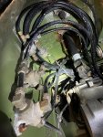
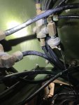
Here's a couple of pics of the under side of the drivers footwell. Just to the left of the steering shaft are three valve/manifolds. The bottom two are bolted to the sheet metal with a couple of bolts through a mounting flange. The top one has no flange and no mounting bolts.

The air is coming from between the valve/manifold and the sheet metal.

Looking at the outside of this, it would appear to be the area just above the window washer reservoir, but there is nothing there when looking at the outside.

What is that top manifold/valve doing/for? Is it passing air through the sheet metal to somewhere (otherwise how would there be a leak there)? How does it come off?

It only leaks air when the shop air is connected as far as I can tell.


IMG_2173.jpgIMG_2174.jpg
 

Ronmar

Well-known member
3,883
7,549
113
Location
Port angeles wa
All three of those are 2way check valves. They allow control of the brake systems by either the truck controls or the front gladhand.

The bottom two are for front and rear service brakes and connect to pedal and blue service glad hand then back to those brake systems.

The top one is for park brake, and connects to park brake control, front red emer glad hand and back to feed the park system. The pressure switch seen on the top valve controls your dash park/emer light…

They don't feed thru the sheetmetal…. They are easiest accessed with the cab tilted, or the top one is really easy to access with the grill removed…
 
Top
AdBlock Detected

We get it, advertisements are annoying!

Sure, ad-blocking software does a great job at blocking ads, but it also blocks useful features of our website like our supporting vendors. Their ads help keep Steel Soldiers going. Please consider disabling your ad blockers for the site. Thanks!

I've Disabled AdBlock
No Thanks