• Steel Soldiers now has a few new forums, read more about it at: New Munitions Forums!

  • Microsoft MSN, Live, Hotmail, Outlook email users may not be receiving emails. We are working to resolve this issue. Please add support@steelsoldiers.com to your trusted contacts.

How close do you have to "balance" the load on MEP generators in 240v mode?

Valence

Well-known member
Steel Soldiers Supporter
2,112
555
113
Location
Davis County, UT
USA homes run 120/240v split, single phase (I believe that's the correct terminology). I have read multiple posts of very good information from @Isaac-1 about the MEP-701A/016B generator (the first military generators I've owned):

Examples:
https://www.steelsoldiers.com/threads/tm-and-wiring-question-for-mep701a-16b.129612/#post-1605067
https://www.steelsoldiers.com/threads/mep-016b-mep-701a-a-c-hookup-confusion.56556/#post-656941

In the case of my MEP-701/016B 3kw generator(s), that gives me 32A in 120v mode, or two 16A 'legs' (L1 & L2) in 240v mode.
In the case of my new-to-me MEP-803A 10kw generator, that gives me 104A in 120v mode, or two 52A 'legs' (L1 & L2) in 240v mode

My question are:
  • I assume all MEP generators are like this for 240v mode...(?) (meaning they are a true 240v, not 120/240V split single phase)
  • How close do you have to "balance" the load?
    • For example:
      • In 240v mode on my 3kw, can I pull 5A on L1 and 15A on L2 and not hurt the 3kw generator?
      • In 240v mode on my 10kw, can I pull a total of 5A on L1 and 40A on L2 and not hurt the 10kw generator?
      • Or do you need to pull, as close as possible, the same amperage on each leg?
    • I definitely understand to not exceed the amperage available on each leg. That is clear as day.
 
Last edited:

DieselAddict

Well-known member
Steel Soldiers Supporter
2,541
2,090
113
Location
Efland, NC
If the generators are being used for PRIME power its worth keeping the load balanced. For short term, emergency power use, don't worry about it. Run it like you need to. It won't really care from a health standpoint so long as you aren't overloading any single phase.

You are correct that when you are in 240v split-phase config you can only pull half the total output on each 120v leg. In the case of the 803, if you pull 52A between L1 and N AND 0 between L3 and N, then you are fully loaded.

For the 80x series only the 831, 802, and 803 can be configured for 240v split phase. All the other generators in the series are 3 phase only.
 

Scoobyshep

Well-known member
1,160
1,583
113
Location
Florida
USA homes run 120/240v split, single phase (I believe that's the correct terminology). I have read multiple posts of very good information from @Isaac-1 about the MEP-701A/016B generator (the first military generators I've owned):

Examples:
https://www.steelsoldiers.com/threads/tm-and-wiring-question-for-mep701a-16b.129612/#post-1605067
https://www.steelsoldiers.com/threads/mep-016b-mep-701a-a-c-hookup-confusion.56556/#post-656941

In the case of my MEP-701/016B 3kw generator(s), that gives me 32A in 120v mode, or two 16A 'legs' (L1 & L2) in 240v mode.
In the case of my new-to-me MEP-803A 10kw generator, that gives me 104A in 120v mode, or two 52A 'legs' (L1 & L2) in 240v mode

My question are:
  • I assume all MEP generators are like this for 240v mode...(?) (meaning they are a true 240v, not 120/240V split single phase)
  • How close do you have to "balance" the load?
    • For example:
      • In 240v mode on my 3kw, can I pull 5A on L1 and 15A on L2 and not hurt the 3kw generator?
      • In 240v mode on my 10kw, can I pull a total of 5A on L1 and 40A on L2 and not hurt the 10kw generator?
      • Or do you need to pull, as close as possible, the same amperage on each leg?
    • I definitely understand to not exceed the amperage available on each leg. That is clear as day.
The closer to balanced the less wasted energy, in an electrical distribution system the neutral (L0) carries the unbalanced load back to the source. Example: if you draw 10 amps on 1 leg and 7 on the other the neutral is carrying 3 amps back to the source and is not performing the work it is capable of.

Head damage occurs when one leg is taking a very light/no load) and the other is heavily loaded. This takes alot of time to happen. Raw numbers, I couldnt tell you as I have never abused a set to test it. Run what you need, If it is really unbalanced, either move something or add a load (halogen work light heater etc)
 

Valence

Well-known member
Steel Soldiers Supporter
2,112
555
113
Location
Davis County, UT
If the generators are being used for PRIME power its worth keeping the load balanced. For short term, emergency power use, don't worry about it. Run it like you need to. It won't really care from a health standpoint so long as you aren't overloading any single phase.

You are correct that when you are in 240v split-phase config you can only pull half the total output on each 120v leg. In the case of the 803, if you pull 52A between L1 and N AND 0 between L3 and N, then you are fully loaded.

For the 80x series only the 831, 802, and 803 can be configured for 240v split phase. All the other generators in the series are 3 phase only.
Thank you. Also, I didn't know the 831 was capable of split 240v. I see them from time to time. Good to know!


The closer to balanced the less wasted energy, in an electrical distribution system the neutral (L0) carries the unbalanced load back to the source. Example: if you draw 10 amps on 1 leg and 7 on the other the neutral is carrying 3 amps back to the source and is not performing the work it is capable of.

Head damage occurs when one leg is taking a very light/no load) and the other is heavily loaded. This takes alot of time to happen. Raw numbers, I couldnt tell you as I have never abused a set to test it. Run what you need, If it is really unbalanced, either move something or add a load (halogen work light heater etc)
Ahhhhh, that makes perfect sense about the wasted energy part. What constitutes as "heavily loaded"? 10A? 15.99?

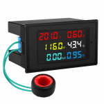
My generator is a ways from my house. I'm going to add a display meter to my circuit breaker panel to tell me the load on each leg. Maybe even a smart meter of sorts like below:

Examples:
1644976608623.png
https://smile.amazon.com/DROK-Frequency-Electric-Voltmeter-Multimeter/dp/B07YC1XHKQ/

1644976632205.png
https://smile.amazon.com/Emporia-Monitor-Circuit-Electricity-Metering/dp/B08CJGPHL9/
 
Last edited:

DieselAddict

Well-known member
Steel Soldiers Supporter
2,541
2,090
113
Location
Efland, NC
I think we need to be careful saying that neutral current is wasted or does not do work. Neutral current is the result of the imbalance between the two split phases but neutral current does do work and is not wasted.
 

Scoobyshep

Well-known member
1,160
1,583
113
Location
Florida
I think we need to be careful saying that neutral current is wasted or does not do work. Neutral current is the result of the imbalance between the two split phases but neutral current does do work and is not wasted.
You are welcome to your opinion, and are more than welcome to follow any information you see fit, your loss of efficiency is not my problem.

Yes the neutral current carries the unbalanced load, and without it solidly grounded the voltages would fluctuate to dangerous (to equipment) levels.


Current that returns to the source over the neutral is not doing all the work it can do.
Source: 5 years of electrical apprenticeship, 20 years of master electrician, and 4 years of electrical engineering.


If you would like more information on AC theroy I would be happy to recommend some great literature.


Sent from my SM-G973U using Tapatalk
 

Chainbreaker

Well-known member
1,802
2,009
113
Location
Oregon
Also, depending on how old/new your house breaker panel is, you might be able to get some clues as to how well the electrician did his job of wiring up the panel originally. My house was built in 2005 and the Electrician differentiated each leg by labeling each circuit breaker as being on either "A" or "B" leg. The "A" circuit skips every other circuit breaker if looking top to bottom at breaker panel with the "B" circuit being the other breakers in-between. Of course, the 240 volt breakers use both legs A+B (L1/L3).

I retrofitted digital meters for each leg on my primary house generator and while running that generator I did an audit of the amps each circuit is running when on generator power to monitor load balance. I now have a good idea of typical loading. However, I don't expect to ever get a truly "balanced loading" due to intermittent loads coming & going offline such as well pump, septic pump, espresso machine boiler, freezer/refrigerator compressors, etc. Although, it gives me a good idea if I'm grossly imbalanced for any length of time.

I once played the game of "meter fixation" watching my genset's L1/L3 panel meters & would go inside & turn on other loads in an attempt to better balance the load distribution but it was pretty much futile. By the time I ran inside the house & turned on a compensating load (halogen ceiling lights, hair dryer or whatever I had on the other leg, the opposite leg had dropped one of the loads (refrigerator, freezer, etc.). So, it's a case of "it is what it is" unless your electrician did a really poor job or there were DIY installations that grossly upset the load balance on one leg in particular.

The best value I gained was an understanding if I was ever approaching peak loading on my MEP-002a's 5 KW-7KW load tolerance. I now know to not turn on the outdoor hot tub or electric clothes dryer (both are high wattage 240 volt loads) without temporarily turning off other circuits to stay within my gensets peak output capability.

Edit: I might add that it most important for those wanting to purchase a home backup generator to do an initial complete audit of all the appliances/loads in your home/shop or whatever you are planning to run on generator power BEFORE you select the generator to utilize for the job. In my case, I have propane fired hot water heater, furnace & cooktop stove so that allowed me to stay under the 10 kW threshold with a 5 kW conservative Military genset rating. Had I gone with a non-military commercially available generator I would most likely have looked in the 7 kW range.
 
Last edited:

Coug

Well-known member
Steel Soldiers Supporter
3,003
4,420
113
Location
Olympia/WA
So the example of 10 amps one leg 7 amps the other leg and 3 amps being "wasted"...


The loss here is coming in the transformer, stepping down from line voltage to household voltage. The transformer is designed for 240V out, but has a tap in the middle of it for the 120 "split" that is connected to ground/earth.
In the house wiring, the two legs and a neutral wire are used for the 120V power. As you distribute the load between the two halves of the split, they balance each other out to a degree, but any power imbalance is made up by the neutral. The neutral is tied into the earth/ground in the distribution panel.
Hence, any power used on one half of the split, but not the other half is "wasted" because the transformer is still putting out equal amounts of power to both sides, but it isn't being used. The transformer isn't operating at maximum efficiency, because it's still using up more power via induction, even if it isn't being used.
The wastage comes in along the neutral wire, which goes back to the center tap of the transformer, bypassing the power meter.
See, you're being charged for all the power coming out of the transformer. Any imbalance between the two halves of the split phase goes through the neutral wire, back to the transformer. So even though you didn't utilize that power from the imbalance, you still get charged for it.


Now, for a generator application, the same type of "wastage" doesn't apply the same way. Yes, you're still dealing with sets of wires and induced current, but rather than being the center tapped transformer, you have a rotor/stator providing the power.
The engine is what you are dealing with, not the gen head/windings. You are paying for the fuel going into the engine, not the power coming out.
Even if one leg has 20 amps on it and the other leg has 0 amps, the engine only has to work hard enough to produce the 20 amps on the one leg. The other leg isn't using power, so it's not presenting resistance against the rotating magnetic field created by the rotor, and thus not not actually "wasting" power in the same way that a center tapped transformer does.

So yes, while an unbalanced load is causing power to be "wasted" we don't really care about it from the generator because it isn't doing anything to increase the operating cost of the generator.


EDIT) This is just my understanding of how it all works. I'm not an electrical engineer or electrician; I'm just some guy that makes his living working on standby generators and occasionally helping customers with off grid power systems. I might have some of the details incorrect above, but the overall theory should be decent, if somewhat simplified.
 

Valence

Well-known member
Steel Soldiers Supporter
2,112
555
113
Location
Davis County, UT
So the example of 10 amps one leg 7 amps the other leg and 3 amps being "wasted"...


The loss here is coming in the transformer, stepping down from line voltage to household voltage. The transformer is designed for 240V out, but has a tap in the middle of it for the 120 "split" that is connected to ground/earth.
In the house wiring, the two legs and a neutral wire are used for the 120V power. As you distribute the load between the two halves of the split, they balance each other out to a degree, but any power imbalance is made up by the neutral. The neutral is tied into the earth/ground in the distribution panel.
Hence, any power used on one half of the split, but not the other half is "wasted" because the transformer is still putting out equal amounts of power to both sides, but it isn't being used. The transformer isn't operating at maximum efficiency, because it's still using up more power via induction, even if it isn't being used.
The wastage comes in along the neutral wire, which goes back to the center tap of the transformer, bypassing the power meter.
See, you're being charged for all the power coming out of the transformer. Any imbalance between the two halves of the split phase goes through the neutral wire, back to the transformer. So even though you didn't utilize that power from the imbalance, you still get charged for it.


Now, for a generator application, the same type of "wastage" doesn't apply the same way. Yes, you're still dealing with sets of wires and induced current, but rather than being the center tapped transformer, you have a rotor/stator providing the power.
The engine is what you are dealing with, not the gen head/windings. You are paying for the fuel going into the engine, not the power coming out.
Even if one leg has 20 amps on it and the other leg has 0 amps, the engine only has to work hard enough to produce the 20 amps on the one leg. The other leg isn't using power, so it's not presenting resistance against the rotating magnetic field created by the rotor, and thus not not actually "wasting" power in the same way that a center tapped transformer does.

So yes, while an unbalanced load is causing power to be "wasted" we don't really care about it from the generator because it isn't doing anything to increase the operating cost of the generator.


EDIT) This is just my understanding of how it all works. I'm not an electrical engineer or electrician; I'm just some guy that makes his living working on standby generators and occasionally helping customers with off grid power systems. I might have some of the details incorrect above, but the overall theory should be decent, if somewhat simplified.
Do you have any knowledge if the the military generators are built differently somehow? The way you've explained the theory, it makes it seem like there is no downside to an "unbalanced" load - neither fuel wastage nor damage to the generator (and there are a number of folks/threads that admonish against "unbalanced" loads when in the 240v mode).

I'm wondering if the damage in the "unbalanced" load is just that folks are more prone to overload a single leg..
 
Last edited:

DieselAddict

Well-known member
Steel Soldiers Supporter
2,541
2,090
113
Location
Efland, NC
Do you have any knowledge if the the military generators are built differently somehow? The way you've explained the theory, it makes it seem like there is no downside to an "unbalanced" load - neither fuel wastage nor damage to the generator (and there are a number of folks/threads that admonish against "unbalanced" loads when in the 240v mode).

I'm wondering if the damage in the "unbalanced" load is just that folks are more prone to overload a single leg..
These machines are built a bit different than normal civilian generators. The main thing that I would say is in their favor is they don't skimp on wire size on the load wiring. The generator heads are also heavier duty than a similar capacity civilian machine.
 

Scoobyshep

Well-known member
1,160
1,583
113
Location
Florida
So the example of 10 amps one leg 7 amps the other leg and 3 amps being "wasted"...


The loss here is coming in the transformer, stepping down from line voltage to household voltage. The transformer is designed for 240V out, but has a tap in the middle of it for the 120 "split" that is connected to ground/earth.
In the house wiring, the two legs and a neutral wire are used for the 120V power. As you distribute the load between the two halves of the split, they balance each other out to a degree, but any power imbalance is made up by the neutral. The neutral is tied into the earth/ground in the distribution panel.
Hence, any power used on one half of the split, but not the other half is "wasted" because the transformer is still putting out equal amounts of power to both sides, but it isn't being used. The transformer isn't operating at maximum efficiency, because it's still using up more power via induction, even if it isn't being used.
The wastage comes in along the neutral wire, which goes back to the center tap of the transformer, bypassing the power meter.
See, you're being charged for all the power coming out of the transformer. Any imbalance between the two halves of the split phase goes through the neutral wire, back to the transformer. So even though you didn't utilize that power from the imbalance, you still get charged for it.


Now, for a generator application, the same type of "wastage" doesn't apply the same way. Yes, you're still dealing with sets of wires and induced current, but rather than being the center tapped transformer, you have a rotor/stator providing the power.
The engine is what you are dealing with, not the gen head/windings. You are paying for the fuel going into the engine, not the power coming out.
Even if one leg has 20 amps on it and the other leg has 0 amps, the engine only has to work hard enough to produce the 20 amps on the one leg. The other leg isn't using power, so it's not presenting resistance against the rotating magnetic field created by the rotor, and thus not not actually "wasting" power in the same way that a center tapped transformer does.

So yes, while an unbalanced load is causing power to be "wasted" we don't really care about it from the generator because it isn't doing anything to increase the operating cost of the generator.


EDIT) This is just my understanding of how it all works. I'm not an electrical engineer or electrician; I'm just some guy that makes his living working on standby generators and occasionally helping customers with off grid power systems. I might have some of the details incorrect above, but the overall theory should be decent, if somewhat simplified.
Transformer spot on

Generator, lets assume you are running 20 amps and 0. The field windings have to create a magnetic field strong enough to incuce 20 amps of current and the stronger the field the more work the engine must perform. The unloaded leg is subject to the same strength magnetic field and is picking up the same induced current, current that can be better utilized. Now if the head were balanced each winding would be loaded to 10 amps, there is less effort needed to keep the frequency in spec, less engine effort is less fuel consumed and you are still getting 20 amps of work out of the generator set.

Sent from my SM-G973U using Tapatalk
 

Coug

Well-known member
Steel Soldiers Supporter
3,003
4,420
113
Location
Olympia/WA
Transformer spot on

Generator, lets assume you are running 20 amps and 0. The field windings have to create a magnetic field strong enough to incuce 20 amps of current and the stronger the field the more work the engine must perform. The unloaded leg is subject to the same strength magnetic field and is picking up the same induced current, current that can be better utilized. Now if the head were balanced each winding would be loaded to 10 amps, there is less effort needed to keep the frequency in spec, less engine effort is less fuel consumed and you are still getting 20 amps of work out of the generator set.

Sent from my SM-G973U using Tapatalk
yes, it can be better utilized, but the net cost of the imbalance in fuel usage is extremely minimal compared to a perfectly balanced load, so in practical application, it's not really an issue.
 

Coug

Well-known member
Steel Soldiers Supporter
3,003
4,420
113
Location
Olympia/WA
Do you have any knowledge if the the military generators are built differently somehow? The way you've explained the theory, it makes it seem like there is no downside to an "unbalanced" load - neither fuel wastage nor damage to the generator (and there are a number of folks/threads that admonish against "unbalanced" loads when in the 240v mode).

I'm wondering if the damage in the "unbalanced" load is just that folks are more prone to overload a single leg..
Well, yeah, damage from unbalanced loads IS because a single leg is being overloaded. As for how people do it, on a 5kw especially, it's really easy to overload as you're talking about 22 amps of 120 per leg, which is a couple small space heaters, before you're more than that.


So most civilian generators will specifically state on them things like "maximum 50% load imbalance" or something similar. Once you load over that 50%, the wires aren't rated for the current and heat buildup can cause issues.

In the military gens, the gen stator alone weighs more than most civilian gensets of the same output. Of course, we're talking about 12 sets of windings in it instead of 2 because of the selectable output feature. I'm not 100% clear on how all the different connections actually work to give you all the different outputs.

I don't actually know if these things are rated to run at more than 50% load imbalance in 120/240 operation, so I can't give advice on that. I would say that no generator really likes being imbalanced.
 

Scoobyshep

Well-known member
1,160
1,583
113
Location
Florida
I can only provide you answers based on physics and best practice, You are entirely welcome to do things your way it has no bearing on my day to day life.
 

NATCAD

Active member
241
50
28
Location
Port Huron Michigan
Do you have any knowledge if the the military generators are built differently somehow? The way you've explained the theory, it makes it seem like there is no downside to an "unbalanced" load - neither fuel wastage nor damage to the generator (and there are a number of folks/threads that admonish against "unbalanced" loads when in the 240v mode).

I'm wondering if the damage in the "unbalanced" load is just that folks are more prone to overload a single leg..
OP Remember you don't have 240. You have 120/240 split phase.

yes, it can be better utilized, but the net cost of the imbalance in fuel usage is extremely minimal compared to a perfectly balanced load, so in practical application, it's not really an issue.
well... that sounds like we need a fuel test to confirm! I wonder if it would be evident with 50 amps on one leg and 10 on the other in 120/240. I don't really want to run the generator with that wide a load imbalance to find out 'the science' (as the fearless leaders seem to call it these days). An imbalance I might see in reality is 55 amps on l1 and 65 on l2. I'm guessing in that situation the fuel consumption difference WOULD be minimal as you have said.
But what do we compare the load imbalance to? a perfect 50/50 split? i.e. 50 amps l1 and 50 amps l2
And would the efficiencies be more apparent at full loading or part loading?
 

DieselAddict

Well-known member
Steel Soldiers Supporter
2,541
2,090
113
Location
Efland, NC
I appreciate the dialog here. I'm going to share my understanding. I hope its clear that I'm not trying to argue. Exchanging information is always an opportunity for everyone involved to maybe take something away from the conversation.

Transformers and generators are fundamentally different kinds of sources. Imbalanced loads affect them differently. On the load side of our residential power systems, neutral current has zero impact on anything downstream of the source so long as your neutral is sized correctly and aren't suffering from excessive voltage drop due to going cheap on the wire.

Imbalanced loads in transformers affects efficiency. SLIGHTLY. In modern transformers it doesn't affect it much. Maybe 1-2%. Not enough to matter and not really our concern since that transformer belongs to the utility. To get more specific as to WHY it affects efficiency, its due to eddy currents in the core caused by the asymmetrical loading of the windings. Those eddy currents are dissipated as heat. If you are consuming 15kw off of a single leg of the transformer you are causing maybe 200 w of extra heat dissipation in the transformer. If an extra 200w of heat is a problem, you have the wrong transformer. Its not an issue.

For generators its a different impact. There is no large iron core to develop those kind of eddy currents. Current imbalances manifest themselves as phase voltage imbalances. It doesn't hurt the generator so long as the current limits for conductors and connectors are respected. To be more specific to the MEPs, its not going to hurt them. The AVR in the MEP802/3 senses voltage between L3 and L0. This means that the voltage between L1 and L0 will float up and down depending on the size of the imbalanced load. If you put more load between L3 and L0 the AVR will boost excitation and the voltage between L1 and L0 will rise above the voltage of L3-L0. Consequently if you load up L1-L0 then its voltage is going to droop some in comparsion to L3-L0. Its not going to vary a LOT but it will vary. So long as we are not overloading either 120v leg, there is no real impact to the generator. If we want to go and stretch for an impact we COULD get a little more heat in the neutral which is a loss versus loading between L1-L3 but again, its negligible.

To demonstrate how the AVR reacts to load imbalances, I'm going to do a test and document the behavior using my MEP803 and A427A load bank. I'll load up L1-L0 and then L3-L0 and record the results.
 

Guyfang

Moderator
Staff member
Moderator
16,920
24,537
113
Location
Burgkunstadt, Germany
Now for my 2 cents worth. I am just a simple Generator Mechanic. High school grad, by the hair of my chinny, chin, chin. No collage to speak of. But after 20 years of running Army Generators, will tell you, an imbalanced load is no big thing. Unless its a very large imbalance. We ran 24/7 and 365 days a year, with imbalanced loads. Nothing ever went wrong. Because it was kept down to a dull roar. For your needs, unless you intend to replace the electric company, don't worry about it.
 

Valence

Well-known member
Steel Soldiers Supporter
2,112
555
113
Location
Davis County, UT
I really appreciated the discussion and what I've been able to learn from everyone here! Thanks!

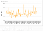
I have embarked upon information gathering spree since I had no real knowledge of what my usage was, beyond my monthly electric bill. I have kept my city utility bills since I bought my home over a decade ago. I've entered everything into a massive spreadsheet and created several graphs, such as this one:
1645503893853.png

Though that info seemed more applicable to home solar and battery backup planning (quite out of my budget at the moment) and not really that helpful for my generator questions. Specifically, what individual circuit demands/usages were, let alone the startup amperage requirements of my various appliances.

I found the coolest tool for that: Emporia Smart Home Energy Monitor
https://smile.amazon.com/Emporia-Monitor-Circuit-Electricity-Metering/dp/B08CJGPHL9
1645509279492.png

It requires 2.4GHz WiFi, an internet connection, and a smart/mobile device to display on via their free App. That's the downside, is that Emporia's servers are needed.
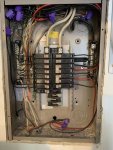
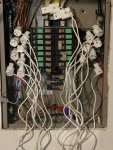
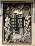
Each sensor simply clips on each one of your input lines and circuits. It does make for a lot of wires in your circuit breaker box though.
$150 for sixteen 50A sensors and two 200A main sensors, WiFi antenna - all quality construction - seemed like really good value. I have been really impressed with this, and the app.

01.jpg 02.jpg 03.jpg

The app lets you label each circuit as you want, and even add a multiplier so you only need 1 sensor for the 240v appliances (just add a 2x multiplier). You can change the units of measurement from the default of Watts, to Dollars (if you input your electric billing rates), Amps and several others (this Home Energy Monitor has been designed to work well with homes with solar panels, electric vehicles and more). I prefer to set the units to Amps because that's more applicable to my generator, and plus, then the app will show you the total of each A or B leg:
04.png

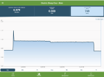
As seen here on my tablet, I can see the spike (in Watts) for my furnace startup and its running characteristics:
05.png

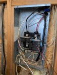
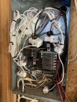
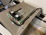
My house has a separate circuit breaker panel in the garage, so I bought an 8 sensor kit for it too. However, that install didn't turn out quite as nice because its circuit breaker box was smaller and was poorly organized by the previous owners who wired it (in the course of doing this I found that they never connected the neutral line for the air compressor nor the ground wire for the circuit I used for my welder. Nice job idiots! When you buy a place, inspect the wiring closely!)
10.jpg 11.jpg

Adding this second monitor, I was able to see that the startup power for my 240v air compressor was over 5kw (40-50 Amps). So I'd definitely need a 10KW generator to start that air compressor!
12.png

Moral of the story here, is that I've been able to see exactly what my individual circuit and total Amperage usage is. It turned out that, in my opinion, my most used circuits in my house were all on leg 'A', including the furnace. So I moved my fridge/microwave, freezer, TV, and work room lights over to leg 'B' so those appliances wouldn't be spiking current draw at the same time as the furnace on leg 'A'.
 
Last edited:

Valence

Well-known member
Steel Soldiers Supporter
2,112
555
113
Location
Davis County, UT
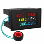
I took this one step further. When running my home from my generator, my generator is some distance from the house. So I wanted to double check the voltage and frequency that the generator was producing, before energizing my circuits, as well as monitor amperage load on each leg. The Emporia Home Energy Monitor does the latter for me (amperage monitor), but I cannot guarantee that when I'm on generator power that I'll have internet access to access the data from their servers. So I needed another way to see this information instantaneously/locally.

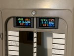
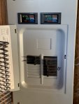
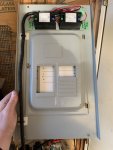
So I cut the front of my circuit breaker panel to install these LCD display meters:
https://smile.amazon.com/DROK-Frequency-Electric-Voltmeter-Multimeter/dp/B07YC1XHKQ/
1645509205973.png

I don't feel that they're all THAT accurate (cheap Chinese manufacture after all) but they'll be close enough for my needs. The one I tested read 120.4v when my Fluke multimeter read 119.9v which is well within the claimed 1-2% error. I do have concerns how long they'll last, but we'll see I suppose.

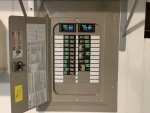
I also installed the displays on their own breakers so I can have all the house off and turn on just the display meters to verify correct voltage and phase from the generator, then start turning on other circuits while monitoring the Amperage load on each leg.
20.jpg 21.jpg 22.jpg
(The green tape with numbers on the circuit breakers is to tell me what Emporia Sensor # is where since the numbering got a bit out-of sync with the additional circuit breakers)

I did the same with the garage, but I still need to get separate breakers for the display meters.
23.jpg 24.jpg
 
Last edited:
Top
AdBlock Detected

We get it, advertisements are annoying!

Sure, ad-blocking software does a great job at blocking ads, but it also blocks useful features of our website like our supporting vendors. Their ads help keep Steel Soldiers going. Please consider disabling your ad blockers for the site. Thanks!

I've Disabled AdBlock
No Thanks