Gunfreak25
Well-known member
- 1,561
- 620
- 113
- Location
- Yuma, AZ
As before, each paragraph corresponds with each picture below. From left to right.
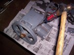
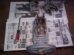
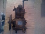
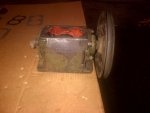
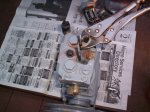
I disassembled, cleaned and reasembled this compressor last year since it came to me seized up from sitting for so many years outside. A hone job and a little rust removal had it back in action, the bottom end and crankshaft roller bearings looked like new. Now that the M211 has a solid 6.2 in it, I thought I would take the time to disassemble this compressor again to make sure it is in tip top shape before going on the 6.2. The compressor will received pressurized oil from the plugged port above the oil cooler lines. I am using the stock M211 in tank fuel pump, and made a blockoff plate to cover up the old hole in the block for the mechanical lift pump. This plate is tapped for a fitting as well, and is where the compressor will drain the engine oil back into the 6.2's oil pan. This also means the oil is run through the 6.2's oil filter before being reintroduced into the oiling system.
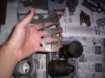
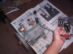
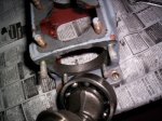
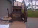
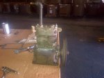
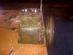
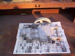
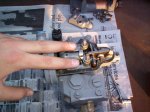
Here is our GMC air pump
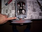
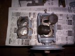
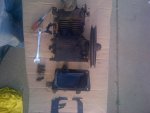
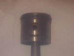
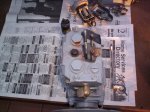
Start by removing the 4 oil pan bolts.
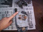
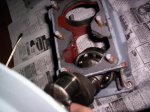
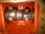
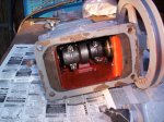
This is what the bottom end looks like.
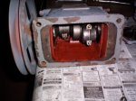
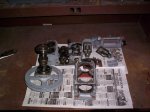
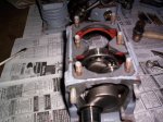
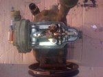
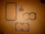
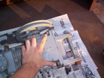
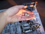
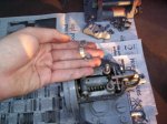
Next remove the air governor by removing the 2 locknuts on top.
Next remove these 2 nuts holding down the metal band.
Remove the band.
Remove the bushings.
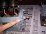
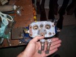
Governor removed. Further disassembly is not needed. If it's gummed up, spray it out with brake parts cleaner.
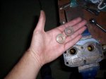
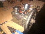
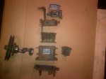
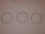
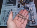
Next remove the two push rods/springs.
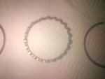
The compressor uses studs, not bolts. A bolt applies a twisting force, which means overtime it will stretch depending on how much load it's subject to (engine head bolts for example). Head bolts are TTY (torque to yield) and as such they must be thrown away after each use. Studs are superior for this type of work as they provide a much stronger, more reliable clamping force. A bolt uses the threads to apply clamping force, on a stud the nut is what does all the clamping. Studs are re useable, too! Studs are always installed finger tight only. No need to use vice grips. If they don't install easily, clean your threads with a tap!
I disassembled, cleaned and reasembled this compressor last year since it came to me seized up from sitting for so many years outside. A hone job and a little rust removal had it back in action, the bottom end and crankshaft roller bearings looked like new. Now that the M211 has a solid 6.2 in it, I thought I would take the time to disassemble this compressor again to make sure it is in tip top shape before going on the 6.2. The compressor will received pressurized oil from the plugged port above the oil cooler lines. I am using the stock M211 in tank fuel pump, and made a blockoff plate to cover up the old hole in the block for the mechanical lift pump. This plate is tapped for a fitting as well, and is where the compressor will drain the engine oil back into the 6.2's oil pan. This also means the oil is run through the 6.2's oil filter before being reintroduced into the oiling system.
Here is our GMC air pump
Start by removing the 4 oil pan bolts.
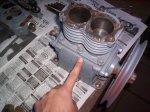
This is what the bottom end looks like.
Next remove the air governor by removing the 2 locknuts on top.
Next remove these 2 nuts holding down the metal band.
Remove the band.
Remove the bushings.
Governor removed. Further disassembly is not needed. If it's gummed up, spray it out with brake parts cleaner.
Next remove the two push rods/springs.
The compressor uses studs, not bolts. A bolt applies a twisting force, which means overtime it will stretch depending on how much load it's subject to (engine head bolts for example). Head bolts are TTY (torque to yield) and as such they must be thrown away after each use. Studs are superior for this type of work as they provide a much stronger, more reliable clamping force. A bolt uses the threads to apply clamping force, on a stud the nut is what does all the clamping. Studs are re useable, too! Studs are always installed finger tight only. No need to use vice grips. If they don't install easily, clean your threads with a tap!
Attachments
-
 73.2 KB Views: 97
 -
 75.6 KB Views: 108
 -
 82.7 KB Views: 91
 -
 77.4 KB Views: 98
 -
 90.7 KB Views: 103
 -
 67.7 KB Views: 97
 -
 76.3 KB Views: 100
 -
 61.3 KB Views: 99
 -
 86.6 KB Views: 100
 -
 64.8 KB Views: 103
Last edited: