• Steel Soldiers now has a few new forums, read more about it at: New Munitions Forums!

  • Microsoft MSN, Live, Hotmail, Outlook email users may not be receiving emails. We are working to resolve this issue. Please add support@steelsoldiers.com to your trusted contacts.

How to hookup MEP-802A and MEP-003A through Asco transfer switch to dual 200A panels

pclausen

Well-known member
Steel Soldiers Supporter
452
281
63
Location
Afton, VA
Spoke to Emerson Power and S3 DIP 8 needed to be moved from ON to OFF (this is not documented in the manual at all). After that, the Connectivity Module was able to talk to the ATS controller just fine.

Here's the view of the ATS web page:

atsweb.jpg

The Voltage and Frequency reading on the Emergency (Generator) side can be ignored since the terminals are connected to anything yet.

I might fiddle some with the dropout and pickup percentages on the Emergency side based on load testing once I get to that point.

Also, Emerson told me there is indeed a firmware update available but that I'd have to schedule a service call and have one of their techs perform the update. Oh well, guess I'll just putt along on the version I got. Seems to work fine with the Java security exemption I added.
 

pclausen

Well-known member
Steel Soldiers Supporter
452
281
63
Location
Afton, VA
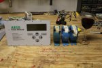
I picked up an Asco Power Manager along with 3 200/5A current transformers. This will allow me to more closely track voltage, frequency and current across L1, L2 and Neutral. Those current transformers are a lot bigger than I expected.

ascopm-01.jpg
http://www.cstone.net/~dk/ascopm-01.JPG

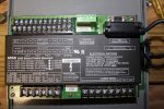
Back side showing all the sensor inputs and relay outputs for doing automated load shedding based on actual current consumption.

ascopm-02.jpg
http://www.cstone.net/~dk/ascopm-02.JPG

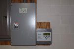
Here's how the Power Manager will be installed, right next to the transfer switch. In all I have to run 6 wires for the current transformers, 3 wires for the voltage sensors and 3 wires for the transfer switch position.

ascopm-03.jpg
http://www.cstone.net/~dk/ascopm-03.JPG

The Power Manager also needs a 24 V DC source to operate. I'm thinking of feeding it from the batteries from one of the generators. This way the Power Manager won't go down during the period between main power being lost and emergency power coming online. My only concern is how much the voltage will drop during engine cranking.

I'm also working on installing under deck roofing where the generators will be located. Wouldn't want the MEPs getting rained on. :)
 

tim292stro

Well-known member
2,118
41
48
Location
S.F. Bay Area/California
That's right - drinking wine and running electrical wires :)

Awesome.

...The Power Manager also needs a 24 V DC source to operate. I'm thinking of feeding it from the batteries from one of the generators. This way the Power Manager won't go down during the period between main power being lost and emergency power coming online. My only concern is how much the voltage will drop during engine cranking...
You can pull power from both 24V battery sets on the generators, and put it through a load sharing board like this. For a start signal ride-through you can just use a capacitor large enough to support the load during cranking - where you can expect to see voltage drop up to as much as 50% or a small DC UPS like this (or just run a 24V wall-wart from the "emergency load panel" and go through the DC UPS...).
 
Last edited:

pclausen

Well-known member
Steel Soldiers Supporter
452
281
63
Location
Afton, VA
Lol. The wine glass was really more for scale. Once thing is for sure, the power will be off when wiring the current transformers! Those secondaries can pack quite a punch when open.

That load sharing board looks cool, but I'm toying with the idea of connecting the 2 generators via the 24 volt powers they both have. Unfortunately the 802 uses a different 24 volt port compared to the 003, but if I can fine one of each connector, that might work.

If I use a capacitor, I would need to put a diode inline between it and the battery to prevent to starter motor from draining it, right? I do have a pair of 3k UPSs sitting in one of my equipment racks about 30 feet from where the transfer switch is, so I might just run AC power from there to a 24 V AC adapter and be done with it that way.

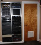
Here are those guys with some other power hungry components.

powerwhore-01.jpg
http://www.cstone.net/~dk/powerwhore-01.jpg

Does anyone remember cassette and laser disk players, or CD players for that matter? :) These days all my media in ripped onto a pair of 24 disk raid arrays, but sometimes I do miss manually browsing my collection of DVD, Laserdisks, HDDVD and Blu-rays to find something to watch.
 
Last edited:

tim292stro

Well-known member
2,118
41
48
Location
S.F. Bay Area/California
That looks familiar - I used to do home theater installations in the 90's. Yes, I recall LaserDisc - nothing like composite video the size of an LP with RF digital audio out... talk about engineering compromises. Fun to watch Back to the Future 2 and see them in bales next to a dumpster - maybe Steven Spielberg saw it coming? :)

I still have a copy of the original Star Wars Trilogy in anamorphic-widescreen. That's about the best we can do now that George Lucas isn't selling copies of the trilogy on DVD without the "special education" changes... (no that wasn't a mistake, D@mn you George Lucas!!! D@mn you!!!)


...If I use a capacitor, I would need to put a diode inline between it and the battery to prevent to starter motor from draining it, right?...
That cute load sharing board I linked above is actually two of what they call "Ideal Diodes" - or smart MOSFET management. Both power inputs are already isolated, the load just draws from the most powerful source - you would only have to place a properly sized/rated capacitor after the load-sharing circuit to power the device.

A MOSFET works like a regular diode (the "FETs" they use on that board actually have diodes in them) most of the time, until to apply voltage to the "GATE", at which time it conducts more or less like a piece of wire (vast over simplification). When the GATE is off, the MOSFET will only work like a diode, when the GATE is on it works like a piece of wire. So why use a MOSFET when they have a Diode built in? The diode protects the MOSFET from reverse power (the MOSFET can only take so much voltage in the off state before it gets hurt, it can take up to its rating the "forward" way without getting hurt) - the smarts come in where they measure the voltage across the Diode (built-in) and if it gets to a certain voltage difference it turns on the MOSFET GATE (it's not too high a voltage difference if it is "ON").

Your normal Schottky diode will "consume" about .35-.4 volts, and a normal rectifier diode can consume up to .7 or higher (I've seen 1.4V on some alternator diodes), whereas a MOSFET is similar to a resistive load (usually in the milliohm range) - this means that if you are moving a lot of current it's better to use a 9mOhm MOSFET than a Diode due to the math:

V = I x R
Where "V" - Volts, "I" = current, and "R" = resistance (ohms).

and

P = V x I
Where "P" is power (watts), and V/I are the same as above.

At 24Volts and 3Amps running through a circuit, a rectifier diode would use: 0.7V * 3A = 2.1Watts, a Schottky would use 0.35V * 3A = 1.05Watts, while a MOSFET would use (3A * 0.009Ohms = 0.027V) 0.027V * 3A = 0.081Watts. The other side effect is that unlike a diode which always needs to consume that forward voltage drop (1.4, 0.7, 0.4, 0.35) a MOSFET with it resistive characteristic will actually use up less power the lower the current draw gets. That same 9miliohm MOSFET when only 0.5 amps are going across it: 0.5Amps * 0.009Ohms = 0.0045Volts. I don't know if you're familiar with series circuits, but think of a DIODE or MOSFET as the IRS: "they want their cut" of the system voltage. This means if you put in a smart MOSFET circuit instead of a simple DIODE, as the charge current of the capacitor tapers off due to its time constant - it will actually get in the way less of the system voltage (taking less as the current tapers off). This is great for charging a Capacitor!

I'm using an Ideal Diode circuit to charge engine starter caps in my XM1027 project when I get to that point - it's better than a diode bridge in the way I describe, and what's more it is better at burst power delivery than a battery (so long as it has a battery and an alternator to back it up). It should stretch the life of the Odyssey batteries I plan to install ($$$). Check out what this guy did with a few used Maxwell UltraCaps (I'll need twice as many for 24V and a expect to purchase new):

 
Last edited:

pclausen

Well-known member
Steel Soldiers Supporter
452
281
63
Location
Afton, VA
Wow, those ultra caps are cool! I'm thinking about replacing the batteries in my 3KW UPS with those the next time they go south (one of the UPS is already giving me a warning that its time to replace the batteries again.

I'm quite familiar with MOSFET. In fact, I built a 2 x 120W audio amp about 20 years ago that is still going strong. It has less hum and is quieter that my Adcom amps for certain applications. Seem I have plenty of options for keeping the Power Manager running during the transition to emergency power!

Speaking of the Power Manager, it go a little bit of work done tonight working on the wiring for the current transformers.

xfer-10-23-01.jpg
http://www.cstone.net/~dk/xfer-10-23-01.JPG

I'm grounding one leg of the secondaries on each of the CTs. The black, red and white wires are for L1, L2 and GND voltage sensors. I'll have 1A fast blow fuses in-line on the L1 and L2 wires.
 

tim292stro

Well-known member
2,118
41
48
Location
S.F. Bay Area/California
...Wow, those ultra caps are cool! I'm thinking about replacing the batteries in my 3KW UPS with those the next time they go south...
It's good for short ride-throughs, but to replace batteries in a 3KW/hr UPS, you'd need lots of them... The big ones I linked are 3Watt/hr each, so you'd need about a 1000 of them (before losses), that 3Watts can either come out quickly (max 15-second crank on an engine, or 15/3600ths of an hour ~300Amps/15seconds), or slowly (1hour would be roughly 1.1Amp continuous). Plenty for letting a generator start up and take a load - and that's similar to the flywheel UPSes.
 

pclausen

Well-known member
Steel Soldiers Supporter
452
281
63
Location
Afton, VA
Yeah, I would need quite a few for the UPS :).

Still waiting on my 24 VDC adapter for the Power Manager.

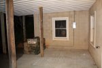
I did get the under deck roofing done and the 003 moved into position under it. Aligning and screwing in metal roofing from below is a royal pain!

I used the forks on the tractor and made a contraption to hold the 18' roofing sections in position while I put in the fasteners.

xferswitch-11-6-01.jpg
http://www.cstone.net/~dk/xferswitch-11-6-01.jpg

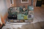
Once the ceiling was done, I moved the 003 into position under it and ran the wiring from the manual transfer switch to it. The 802 will be sitting in front of the basement window.

xferswitch-11-6-02.jpg
http://www.cstone.net/~dk/xferswitch-11-6-02.JPG

For now I'm running the wires along the concrete pad to the terminals. The ground wire goes through the hole in the pallet to the ground lug on the front.

xferswitch-11-6-03.jpg
http://www.cstone.net/~dk/xferswitch-11-6-03.JPG

I fired up the 003 and performed a transfer switch test to put the entire house on the 003. The load according to the meter on the gen set was like 10%. I went through the house and tuned on all the lights, TVs, heat pump to stage 2, got the well pump running ,etc. Went back and looked at the meter, and I was not even at 30% load. The transfer to and from the gen set was so fast that none of my computers noticed or rebooted. I think the only thing that will get even close to getting the 003 to 100%, is if the aux heating elements needs to come on in the heat pump, which will only happen during extremely cold periods.

Now I just need to get one of my 802s running and installed. Spoke to Peter at Inova about his Remote Auto Start board, and it is identical for the 003 and 802 except for one diode required for the 003. So I'll probably pick up the one for the 802 and he will throw in the needed diode for hooking the board up to the 003 initially.

Getting close to wrapping up this project. Once done, I'll see about getting an inspector out to check out my work.
 

pclausen

Well-known member
Steel Soldiers Supporter
452
281
63
Location
Afton, VA
Got tired of waiting on the dedicated 24 VDC power supply for the power manager, so I hooked up my bench DC power supply for now and completed connecting the sensor wires except for the Neutral line CT (get issues with the terminals on it) I'll clean up the wiring a little better later.

asco-11-8-07.jpg
http://www.cstone.net/~dk/asco-11-8-07.JPG

A view from the web interface. I'll need to balance my L1 / L2 loads better. Didn't realize they were this far off.

atsweb2.JPG

Misc front panel readings. These first couple display the same info as the web interface. Btw, KW = Active Power, KVAR = Reactive Power, KVA = Apparent Power. The owners manual goes into a lot of the conventions used to calculate these and other values such as lagging and leading phase angles and that sensing is done up to and including 21st harmonic for true RMS.

asco-11-8-01.jpg

asco-11-8-02.jpg

But then it gets interesting. The Asco Power Manager maintains a log of instant and max watt demand:

asco-11-8-03.jpg

Default window for max watt demand is 15 minutes. I changed it to 1 minute to hopefully capture the peak usage I'll experience a little better.

asco-11-8-04.jpg

There are also 4 relays that can each be triggered by KW demand thresholds:

asco-11-8-05.jpg

It's a shame that it is not possible to access all this via the web interface. I'm hoping it is due to the 10+ year old software versions I'm running on both the communications module as well as on this Power Manager.

asco-11-8-06.jpg

I'll see if I can befriend a local Emerson Power service tech and get the procedure for doing the firmware updates on both devices.

Nevertheless, these are pretty cool toys that can be had for pennies on the dollar compared to what they cost retail.
 
Last edited:

rustystud

Well-known member
9,298
3,074
113
Location
Woodinville, Washington
Lol. The wine glass was really more for scale. Once thing is for sure, the power will be off when wiring the current transformers! Those secondaries can pack quite a punch when open.

That load sharing board looks cool, but I'm toying with the idea of connecting the 2 generators via the 24 volt powers they both have. Unfortunately the 802 uses a different 24 volt port compared to the 003, but if I can fine one of each connector, that might work.

If I use a capacitor, I would need to put a diode inline between it and the battery to prevent to starter motor from draining it, right? I do have a pair of 3k UPSs sitting in one of my equipment racks about 30 feet from where the transfer switch is, so I might just run AC power from there to a 24 V AC adapter and be done with it that way.

Here are those guys with some other power hungry components.

View attachment 523403
http://www.cstone.net/~dk/powerwhore-01.jpg

Does anyone remember cassette and laser disk players, or CD players for that matter? :) These days all my media in ripped onto a pair of 24 disk raid arrays, but sometimes I do miss manually browsing my collection of DVD, Laserdisks, HDDVD and Blu-rays to find something to watch.
Are you kidding ? I still go and look at my collection of "8 tracks" and 45 LP's and 78 LP's !
 

pclausen

Well-known member
Steel Soldiers Supporter
452
281
63
Location
Afton, VA
You're showing your age Rusty! Lol I have a collection of 33's somewhere, but not sure where they are now. I missed the whole 8-track days only being in my 40's now and growing up in Scandinavia. I used to have a reel to reel player that used what looked like thick fishing wire for tape as opposed to the common flat brown stuff.

I got the ATS position sensor properly wired to the Power Manager so it knows if the ATS is on Utility or Emergency power now. It will track how many hours are spent on each.

Here's a shot showing ATS on "NORM"

ascopm-11-10-01.jpg

Looking at my current consumption, with the wife going the dinner thing at the girls playing around with electronics, it is quite a bit higher that I thought.

ascopm-11-10-02.jpg

But what really blew my mind was looking at the highest 1 minute KW demand over the last 2 days! I really need to upgrade the firmware to a later version as those include a times tamp for each event. I'd like to know when I could have possibly been consuming 19,000 watts!

ascopm-11-10-03.jpg

Looking at my HVAC log for the past week, I think I might have found the issue:

ascopm-11-10-05.jpg

Last night it looks like Aux Heat Stage 3 came on for some reason. My Aux heat has 3 stages (5kw, 10kw and 15kw). Here's a legend:

ascopm-11-10-07.jpg

Doesn't make sense to me why Aux Heat Stage 3 would come on before stage's 1 and 2. Hmm, will need to look into that. 19Kw would most certainly bring a 003 to its knees.

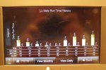
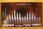
Here's my HVAC run time log for the last year which shows some use of Aux Heat stage 1/2 and a tiny bit of stage 3.

ascopm-11-10-06.jpg

I'll need to do some research to see how to best manage those Aux heat stages unless I want to throw a MEP-805 at it. :)
 
Last edited:

rustystud

Well-known member
9,298
3,074
113
Location
Woodinville, Washington
Yes Peter I know! I remember Walter Cronkite on the news saying Kennedy got shot ! I have over 300 33's .The 78's where my fathers. I used to listen to them growing up. Mostly they are 30's to 40's music. The 45's and 8 tracks are mine also ! I still have this really cool 5 tape deck that would play your 8 tracks for hours ! What a wonder it was ! Five 8 tracks at once ! The person who saw the most Tech change in their life that I know was my grandmother. She was born in 1898. She saw the Wright brothers fly. She rode the first Harley Davidson in the state of South Dakota. It was bought by her uncle. She saw the Moon landing in 1968. She finally died in 1982 .
I'm still waiting for my flying car that I was promised though !
 
Last edited:

csmitty

Member
48
0
6
Location
Atlanta, GA
You're showing your age Rusty! Lol I have a collection of 33's somewhere, but not sure where they are now. I missed the whole 8-track days only being in my 40's now and growing up in Scandinavia. I used to have a reel to reel player that used what looked like thick fishing wire for tape as opposed to the common flat brown stuff.

I got the ATS position sensor properly wired to the Power Manager so it knows if the ATS is on Utility or Emergency power now. It will track how many hours are spent on each.

Here's a shot showing ATS on "NORM"

View attachment 526400

Looking at my current consumption, with the wife going the dinner thing at the girls playing around with electronics, it is quite a bit higher that I thought.

View attachment 526402

But what really blew my mind was looking at the highest 1 minute KW demand over the last 2 days! I really need to upgrade the firmware to a later version as those include a times tamp for each event. I'd like to know when I could have possibly been consuming 19,000 watts!

View attachment 526403

Looking at my HVAC log for the past week, I think I might have found the issue:

View attachment 526408

Last night it looks like Aux Heat Stage 3 came on for some reason. My Aux heat has 3 stages (5kw, 10kw and 15kw). Here's a legend:

View attachment 526409

Doesn't make sense to me why Aux Heat Stage 3 would come on before stage's 1 and 2. Hmm, will need to look into that. 19Kw would most certainly bring a 003 to its knees.

Here's my HVAC run time log for the last year which shows some use of Aux Heat stage 1/2 and a tiny bit of stage 3.

View attachment 526410

I'll need to do some research to see how to best manage those Aux heat stages unless I want to throw a MEP-805 at it. :)
Wanted to check in and see how this was all working for you now a few years later, or if you had changed the setup. I like the ASCO switch and they seem a bit easier to find on the grey/used market. My concern was the lake of load shedding capability but the power manager seems like it could control those contactors well. Any issues or things you wish had done better?
 

pclausen

Well-known member
Steel Soldiers Supporter
452
281
63
Location
Afton, VA
Believe it or not, I only just got around to installing the INOVA remote starer PCB in my 003 this past weekend, so everything is finally fully automated. Picked up a 24V 3 stage charger last week as well, to keep my batteries in good shape.

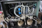
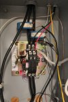
Here's a couple of shots of the INOVA remote start installed in the control housing:

003autostart01.jpg
http://www.cstone.net/~dk/003autostart01.JPG

003autostart02.jpg
http://www.cstone.net/~dk/003autostart02.JPG

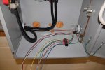
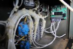
The 2 conductor wire with a red and black lead goes back to the Asco 300 transfer switch and are the thin red and green wires you see in the pic below. When the utility power drops, the contact closes, which in turn puts 24V on TB3 on the INOVA PCB, which kicks of the starting sequence.

003autostart03.jpg
http://www.cstone.net/~dk/003autostart03.JPG

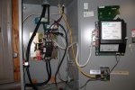
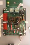
The transfer switch is controlled via this board in the transfer switch housing:

003autostart04.jpg
http://www.cstone.net/~dk/003autostart04.JPG

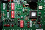
Some better close up shots showing the many DIP switch settings I had to tweak to get it just right.

003autostart06.jpg
http://www.cstone.net/~dk/003autostart06.JPG

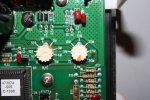
Trim pots to set the delay before switching to Emergency Power, and for setting how long to wait before going back:

003autostart07.jpg
http://www.cstone.net/~dk/003autostart07.JPG

1st engine exerciser test running

003autostart05.jpg
http://www.cstone.net/~dk/003autostart05.JPG

Some functions are replicated between the INOVA unit and the Asco, but I got everything running the way I like now.

Next up will be to gain access to the Asco Connectivity Module and Power Manager. My LAN has been completely redone over the last 2 years. Keeping my fingers crossed that I can still connect a contemporary web browser to the circa 2004 http server embedded with in the Connectivity Module. I had all kinds of Java issues 2 years ago, which I'm sure have not gotten better...
 
Last edited:

csmitty

Member
48
0
6
Location
Atlanta, GA
Nice. Thanks for the pics. What would you say is replicated between the two control sources?

I'm looking for the 5220 to activate the load shedding relays I will put in place and would like to be able to turn off the genset if I'm away for two weeks and lose power so it doesn't run till its out of fuel in a day. Just run it a few hours maybe to keep the fridge cold until returning.

Surely updating the software would help. I'm sure there's better out there but for the cost it's pretty powerful it seems.
 

87Nassaublue

New member
116
0
0
Location
Sharpsburg, Ga
Ah yes, that makes sense. I can see why the code was changed. Back on 2012 when we had the derecho storm, we had no power for a week. My folks had a 15kw Generac standby generator, and it would trip when the water heater came at the same time the oven was running and the A/C (old inefficient unit). Not only that, but it the engine failed on day 4 since those Generac Guardians are not continuous duty. I had a 8kw Generac during the derecho and had to be very careful about what I was running and shut it down when it was not needed. A/C was out and the house was hot as ****, and my wife was pregnant at the time. It was not a fun week.... Around my parts we loose power for at least 24 hours in any given year, and lately the average seems to be more like 3+ days.
I had a 25kw generac generator backing up a data center I was managing. I had issues with it because the electronic governor didn't like a 100% electronic load. The governor would go nuts and the UPS would never connect to it. I had to have a 5kw load back built to stabilize it. It ran OK after that, but I was never thrilled with Generac after that.
 

vprinc

New member
9
1
1
Location
Phoenix, Az.
I am installing a similar setup. I have an ASCO series 300 225 amp with a MEP 803a and Inova auto start board. I was looking to get more detail on how to wire the power manager module with the current transformers. Appreciate any help you could provide based on your experience.
 

TrailLifeBill

Member
Steel Soldiers Supporter
178
4
18
Location
Brunswick, GA
I am installing a similar setup. I have an ASCO series 300 225 amp with a MEP 803a and Inova auto start board. I was looking to get more detail on how to wire the power manager module with the current transformers. Appreciate any help you could provide based on your experience.
If you don't mind, when you get started - please start a thread documenting your install. Many of us read/learn/tweak our installs based on what we read on the forum. Good luck!!
 

DieselAddict

Well-known member
Steel Soldiers Supporter
2,543
2,095
113
Location
Efland, NC
I am installing a similar setup. I have an ASCO series 300 225 amp with a MEP 803a and Inova auto start board. I was looking to get more detail on how to wire the power manager module with the current transformers. Appreciate any help you could provide based on your experience.
Just want to point out that using a 225a automatic transfer switch with a 10kw generator is against code without active load shedding on your downstream panels.
 
Top
AdBlock Detected

We get it, advertisements are annoying!

Sure, ad-blocking software does a great job at blocking ads, but it also blocks useful features of our website like our supporting vendors. Their ads help keep Steel Soldiers going. Please consider disabling your ad blockers for the site. Thanks!

I've Disabled AdBlock
No Thanks