• Steel Soldiers now has a few new forums, read more about it at: New Munitions Forums!

  • Microsoft MSN, Live, Hotmail, Outlook email users may not be receiving emails. We are working to resolve this issue. Please add support@steelsoldiers.com to your trusted contacts.

I need help with a fuel problem with a MEP 802A

ECS

Member
87
50
18
Location
Florida
I have an 802 and it is not getting fuel to the injectors.

Can someone please help with what I need to do next?

I am getting fuel all the way to that governor shut off that is attached to the high pressure fuel pump.
The part that kills the fuel to the diesel engine.
I have fuel going into that governor part but no fuel coming out of the pressure pump and going to the injectors.

The arm on the governor does turn back and forth and I didn't notice weird about it.
The electric arm that controls the engine shut off that is attached to the governor is function as it should, and when you go to start it, the arm pulls back it free up the governor. The when you turn it off it swings back and shut the governor.


I picked up this MEP 802A with 12 hours on it. This is not a rebuild it has only 12 hours.

When I got it it was missing the oil filter and the main breaker behind the instrument panel was popped.

I add oil, anti freeze, oil filter, fuel and reset the breaker behind the panel.
It turn over but will not start because the injectors are not getting fuel.
 

Attachments

Guyfang

Moderator
Staff member
Moderator
16,766
24,082
113
Location
Burgkunstadt, Germany
You are getting the wagon before the horse here. Dont start at the governor,. This is a fuel problem. If I understand your explanation, you have fuel to the IP's, Injector pumps. But nothing to the Injectors. Have you pulled off the supply hose to the IP's? If so, did you get lots of fuel, with the S1 in the run position? If you got lots of fuel to the IP's, then you need to remove the IP's and clean them. Click on this thread. Go to the first message. Read what is in it, to understand what you need to do to test the IP's and clean them. AND, more important, reinstall them right.

MEP-803A won't start
 

ECS

Member
87
50
18
Location
Florida
You are getting the wagon before the horse here. Dont start at the governor,. This is a fuel problem. If I understand your explanation, you have fuel to the IP's, Injector pumps. But nothing to the Injectors. Have you pulled off the supply hose to the IP's? If so, did you get lots of fuel, with the S1 in the run position? If you got lots of fuel to the IP's, then you need to remove the IP's and clean them. Click on this thread. Go to the first message. Read what is in it, to understand what you need to do to test the IP's and clean them. AND, more important, reinstall them right.

MEP-803A won't start

Thanks !!!

Yes I have fuel to the IP and not out of them. I thought it was odd as both do not have fuel out of them; so I was unsure where to go next.
 

ECS

Member
87
50
18
Location
Florida
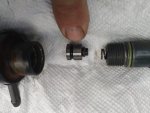
I took the injector pump apart and it seems OK but it look like it is missing o-ring.

When I work the piston it is not pumping fuel.

In this pic is there suppose to be an o-ring here?
If so what kind of o-ring? would anyone know the part number or size or where to get one?
 

Attachments

Last edited:

Ray70

Well-known member
2,595
5,910
113
Location
West greenwich/RI
Hello ECS, FYI, that's the metering pump you took apart, not an injector. I don't think there are any o-rings in the metering pumps, but not 100% positive. There might be an exploded view in the TM.
Take a look at the spring down the bottom, make sure it isn't stuck in the compressed position. You should have 2 1/4" from the tip of the spring to the bottom of the pump's mounting plate. If you have less the pump is stuck and needs to be cleaned. Also, is the lever and pin moving freely? This is what attaches to the fuel rack to adjust and shut off fuel flow out of the pump.
 
  • Like
Reactions: ECS

jamawieb

Well-known member
1,437
556
113
Location
Ripley/TN
With 12 hours, your plunger is more than likely stuck. This is very common with low hour units. Its easier to leave the pumps in place and take the tops off. From your picture, it looks like you may have taken the top off only. There is no oring but below the item you thought had an oring is the plunger. 2 things happen when its working properly, the plunger will turn counter clockwise when the shut off solenoid is activated (pulled back) and will go up and down when the motor is cranked over. I usually take the top of the housing off and then move the cut off solenoid to make sure its moving left to right, then I use the dead crank switch to crank the motor over to see if the plungers move up and down.
 

ECS

Member
87
50
18
Location
Florida
Thanks,

The parts all seem to be moving freely, and I think it is the check valve that is stuck shut.

I was trying to find a diagram of all the parts on this IP (injector pump aka Diesel Fuel Metering Fuel Pump Onan 186-6151) but was unable to find one.

So I'm going to soak the part where the check valve is for a day or two and see how that goes.
 

Dieselmeister

Well-known member
Steel Soldiers Supporter
195
273
63
Location
Flagstaff, Az
and I think it is the check valve that is stuck shut.

The little part sticking out the right side of the part you are pointing at, is the check valve (delivery valve). That part should freely move within the part you are pointing at (valve seat). If it's stuck (usually gummed up), soaking it in carburetor cleaner should loosen it up. Keep all pump parts clean; these are all precision parts!
 

ECS

Member
87
50
18
Location
Florida
I'm doing something wrong, but do not know what it is?

I took the IP's (injection pumps) apart cleaned then and now they pump and turn on and off like they should when I swing the pin back and forth. BUT.

I fired it up and it started surging badly and would not turn off. I had to crack the injector lines to turn it off.

When I install the IP #1 (nearest the rad) in it seems to line up with the slot in the rail and the governor functions and turns back and forth freely.

When I install IP #2 the pin does NOT line up with the slut in the rail unless I TURN the governor a little clock-wise and then it seems the pin is in the rail.
BUT when I put the IP #2 in like this the governor does not swing back all the way counter clock wise to turn off the engine.

When I leave IP #2 in place like this and remove IP #1 and turn the governor back and forth, I can feel the rail move and the IP# 2 will wiggle back and forth.
So it seems IP #2 has the pin in the rail slot.
At this point I have not clamped the IP's down yet.


If I just put IP #1 in the governor does swing back and forth and does return all the way counter clock wise to turn off the engine.

To me it seems the slot in the rail is not in the same position for both injectors.
If the slot in the rail for IP #1 is at 7 o'clock the slot for IP # seems closer to 8 o'clock. Is this offset normal?

I have the input lines on both IP's to the right (rear) of the hold down stud. Each in the same position.

Any ideas on what I'm doing wrong here?
 

Ray70

Well-known member
2,595
5,910
113
Location
West greenwich/RI
Do you have the hold down clamps on the pumps and just not locked down tight? If the clamps are not on at all, or they are too loose the pin and lever of the IP will hit the underside of the block ( above the rack ) and bind it up. If one cylinder is on the "Pump" lobe of the cam this condition will be exaggerated because the cam is trying to push up on the pump.
Put the rack fully towards the radiator and get 1 of the pumps in and put the clamp on ALMOST all the way down, so it's just a little loose.
Then verify rack movement. Then do the other pump, leaving it just barely loose. Now see if the rack moves freely still.
 

ECS

Member
87
50
18
Location
Florida
I left the clamps off until I thought the both pins were in the slots, then I clamped them down before running the engine.

I am having the issue when I put in IP #2.
It seems IP #2 will not fall down in place unless I turn the governor a little clock wise moving the rail toward the rear of the engine slightly.
When I do this the IP #2 seems to fall down in place, but then the governor will not return all the way counter clock wise to the shut off position.

The governor not returning all the way does not seem correct to me, should it return all the way?

When it ran it was surging. The frequency buried and went way past 65 Hz, then it would return to about normal and surge again.

What would cause the surging? I have not seen that before.
How do I check that both pins are in place correctly?
 
Last edited:

Ray70

Well-known member
2,595
5,910
113
Location
West greenwich/RI
Normally the throttle lever should return all the way until it hits the stop screw. If the screw has never been fiddled with you might see red marking paint and possibly locking wire on them. The actual stopping of the motor is done by the IP's. So, a stop screw that is out of adjustment or an IP that is rotated too far either direction could account for what you are seeing. Typically the fuel inlet lines will we almost up against the push rod tube as a starting point. I once had a machine where I could not reinsert either IP with the stop lever all the way against the screw. it actually needed to be loosened just a tiny bit ( lever towards fan more ) to get it to drop in.
The surging you are seeing might be an incorrectly adjusted droop setting on the governor. Or it could be evidence that someone else has been messing around in the governor area and may also be why you are having difficulty with the pumps. Probably should read the TM to get an understanding of the droop adjustment ( inside the timing cover accessed through the pipe plug near the throttle lever )
If you have both pumps installed, loosen the clamps slightly and work the fuel shut off lever back and forth. Are both pumps wiggling and trying to rotate slightly? If so that is a good sign that both pins are engaged in the rack.
 

ECS

Member
87
50
18
Location
Florida
.......
The surging you are seeing might be an incorrectly adjusted droop setting on the governor. Or it could be evidence that someone else has been messing around in the governor area and may also be why you are having difficulty with the pumps. Probably should read the TM to get an understanding of the droop adjustment ( inside the timing cover accessed through the pipe plug near the throttle lever )
...

Thanks so much for her help!

I got it running but still have the surging problem.

I installed the IPs correctly and they are in the slots. When I remove then they pump when they are supposed to and turn off when suppose to.
The manual I have shows the slots this IP pins go in as at 90 degrees to the bar, but the slots are more mike at 70 degrees to the bar.

When it starts it surges really dangerously high rpm, then it drops way below where rpm should run at; then it surges really high rpm again.
It surges and drops, and surges and drops.

How do I adjust the droop on the governor? Do I need to pull the rad fan and cover to do this?
i.e. do I need to remove the the rad. fan and timing cover to adjust this droop through the pipe plug near the throttle level?

I'm lost on the surging.
 

Ray70

Well-known member
2,595
5,910
113
Location
West greenwich/RI
No need to pull the cover to adjust droop. Check the TM and find the droop adjustment procedure.
There is a hex key pipe plug in the timing cover right near the throttle linkage.
Remove that plug and there is a hex key screw that you access through the hole.
The TM tells you what size hex keys they are and it explains how to adjust the droop.
If you are unable to correct the problem by doing the adjustment than there might be a problem internally with the governor weights or the springs.
To access the governor components you will need to remove the belt, crank pulley and timing gear cover.
 
Top