• Steel Soldiers now has a few new forums, read more about it at: New Munitions Forums!

  • Microsoft MSN, Live, Hotmail, Outlook email users may not be receiving emails. We are working to resolve this issue. Please add support@steelsoldiers.com to your trusted contacts.

I need to borrow an 87-89 USAF dual circuit master cyl. mount temporarily

peashooter

Well-known member
1,038
205
63
Location
Hanover, minnesota
CAD File for Master Cylinder Bracket

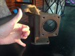
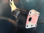
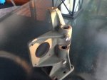
Well Clinto was able to obtain a new Dual Circuit Master Cylinder Bracket. We modeled it up in 3D CAD....and then ran out of time to put much additional effort into the project for the time being. We understand that this is a complex shape and not something likely to be easily duplicated at a cost inline with what most members are willing and able to pay. In an attempt to take advantage of the site's many members who may have creative ways to redesign this in a cost effective way and/or access to discounted manufacturing processes needed, we wanted to share what info we have put together so far (a digital CAD model of the factory bracket). So for you folks who have Fab skills, tools, and access to a CAD software; you can find the files on GRABCAD (a CAD fileshare site). The files are saved in a number of formats, but there are NO DRAWINGS, only 3D CAD files. The 3D files contain all the dimensioning needed.
Please note that the bracket was modeled exactly after the cast bracket. There is a "Simplified" version cad file of the bracket as well that has most of the fillets and drafts removed that are inherent to the cast design. The model should at least give proper dimensions and angles for those who undertake the challenge of redesigning this into an easier to fabricate weldment that will meet form, fit, and function of the original ductile iron casting.
The files can be found here: https://grabcad.com/library/m35a2-dual-circuit-master-cylinder-bracket-1

If anyone finds a good way to reproduce this, be sure to share pics of it!
MC BRACKET ASSY PIC 1.jpgMC BRACKET ASSY PIC 2.jpgMC pic 3.jpgMC pic 2.jpgMC pic 1.jpgView attachment TM Diagram Pics.pdf
 
Last edited:

A Blind Man

Member
Steel Soldiers Supporter
47
9
8
Location
Canton, OH
Awesome! thank you guys so much for all your hard work!
And this is super timely, since I just got my 1100 xzl's so it's time to dig into the axles/brakes/everything else
 

rustystud

Well-known member
9,298
3,072
113
Location
Woodinville, Washington
Well Clinto was able to obtain a new Dual Circuit Master Cylinder Bracket. We modeled it up in 3D CAD....and then ran out of time to put much additional effort into the project for the time being. We understand that this is a complex shape and not something likely to be easily duplicated at a cost inline with what most members are willing and able to pay. In an attempt to take advantage of the site's many members who may have creative ways to redesign this in a cost effective way and/or access to discounted manufacturing processes needed, we wanted to share what info we have put together so far (a digital CAD model of the factory bracket). So for you folks who have Fab skills, tools, and access to a CAD software; you can find the files on GRABCAD (a CAD fileshare site). The files are saved in a number of formats, but there are NO DRAWINGS, only 3D CAD files. The 3D files contain all the dimensioning needed.
Please note that the bracket was modeled exactly after the cast bracket. There is a "Simplified" version cad file of the bracket as well that has most of the fillets and drafts removed that are inherent to the cast design. The model should at least give proper dimensions and angles for those who undertake the challenge of redesigning this into an easier to fabricate weldment that will meet form, fit, and function of the original ductile iron casting.
The files can be found here: https://grabcad.com/library/m35a2-dual-circuit-master-cylinder-bracket-1

If anyone finds a good way to reproduce this, be sure to share pics of it!
View attachment 704584View attachment 704585View attachment 704588View attachment 704587View attachment 704586View attachment 704589
Something else to consider is all the linkage and how it moves around and on the part. If someone could have a video showing a actual bracket installed and all the linkages in motion, it would give someone a good idea what can be removed-added or moved.
 

clinto

Moderator, wonderful human being & practicing Deuc
Staff member
Administrator
Super Moderator
Steel Soldiers Supporter
Supporting Vendor
12,596
1,133
113
Location
Athens, Ga.
Something else to consider is all the linkage and how it moves around and on the part. If someone could have a video showing a actual bracket installed and all the linkages in motion, it would give someone a good idea what can be removed-added or moved.
I can do that next week after the rally is over.
 

JDToumanian

Active member
1,655
14
38
Location
Phelan, CA
Have you guys tried contacting the original manufacturer? It looks like the government ordered them from both AM General and Colonial Sales Co. over the years. They paid $281.15 from AM General and $188.31 from Colonial Sales, in 1993. Getting these cast and machined from the original tooling, if it still exists, would be the best way. Colonial Sales used to be called Colonial Ford Truck Sales of Richmond, VA.... Where did they get these parts from to sell to the government then? Were they reselling surplus? Did they have them made? Could the bracket actually be a Ford truck part that just happened to fit?

http://www.govliquidation.com/auction/haystack?nsn=5340012590257

If they won't sell to us, even in a quantity that a dealer might be interested in to get the price down, it might be possible to force the issue... I got a HEMTT air conditioning mounting bracket out of Oshkosh Defense by going through a vendor that tacks orders on to bigger government orders. It was expensive and took a long time, but I got it... Oshkosh Defense manufactured one obsolete bracket, just for me.

I think you guys are barking up the wrong tree trying to fab that.

Jon
 

Tow4

Well-known member
Steel Soldiers Supporter
2,097
647
113
Location
Orlando, FL
Now, consider an accident. If it is your fault, you're going to get sued. No question. If you have a factory designed system, that's one thing. What could a good lawyer do with a homemade custom system? Do you want to testify that you, with no engineering background and no formal testing system implemented a custom system of your own design?

And that's just the stuff I can come up with off the top of my head, after working for 14 hours today.
Good point. It doesn't matter that you exactly copied the OE, it's not the OEM part.

At that point, you are the manufacturer and will have the liability.
 

JDToumanian

Active member
1,655
14
38
Location
Phelan, CA
I got a HEMTT air conditioning mounting bracket out of Oshkosh Defense by going through a vendor that tacks orders on to bigger government orders. It was expensive and took a long time, but I got it... Oshkosh Defense manufactured one obsolete bracket, just for me.
Just for entertainment, here's the NSN Report for the HEMTT A/C bracket.... Note that on 3/2016, Ruta Supply obtained qty. 1... That is the one I ordered from them. Where there's a will, there's a way. Though the average deuce owner might get sticker shock, to put it in perspective I think about the consequences of a brake failure, or in the case of the A/C bracket, I think of cruising around in my HEMTT in the summer with the windows up... Money well spent.

http://www.govliquidation.com/auction/haystack?nsn=5340015304098

Jon
 

frank8003

In Memorial
In Memorial
6,426
4,985
113
Location
Ft. Lauderdale, Florida
One can have the original ductile iron casting reproduced in whatever metal you want but you need the mould for the metal. You are almost there. Within motorsports they use sand printing. There is a bunch of companies here and abroad that do this work. Bespoke engines for F1,LMP1, LMP2,WRC, WRX, + Moto GP, are made by Grainger and Worrall. Entire engines! The part you want cast is simple compared to what these companies do daily. Look up sand printing. find a foundry that is using it.

https://www.google.com/search?rlz=1C2CHBD_enUS686US691&source=hp&q=sand+printing&oq=sand+printing&gs_l=psy-ab.3..0l2j0i22i30k1l8.58365633.58368911.0.58369468.24.13.0.0.0.0.121.1389.5j8.13.0....0...1.1.64.psy-ab..11.13.1387.0..46j0i131k1j0i46k1j0i10k1.0.QqibCeAbp7c


Well Clinto was able to obtain a new Dual Circuit Master Cylinder Bracket. We modeled it up in 3D CAD....~~~~info we have put together so far (a digital CAD model of the factory bracket). ~~ files on GRABCAD (a CAD fileshare site). The files are saved in a number of formats, but there are NO DRAWINGS, only 3D CAD files. The 3D files contain all the dimensioning needed.
Please note that the bracket was modeled exactly after the cast bracket. ~~~on of the original ductile iron casting.
The files can be found here: https://grabcad.com/library/m35a2-dual-circuit-master-cylinder-bracket-1

If anyone finds a good way to reproduce this, be sure to share pics of it!
View attachment 704584View attachment 704585View attachment 704588View attachment 704587View attachment 704586View attachment 704589
 

JDToumanian

Active member
1,655
14
38
Location
Phelan, CA
Sand printing would be awesome except that it's too expensive, and results in a casting that then needs to be machined. If you had a mill and machined it yourself (or just used a belt sander and drill press), it would probably still cost you around $500...
 

peashooter

Well-known member
1,038
205
63
Location
Hanover, minnesota
We still need a master cylinder for this bracket if it is reproduced. Any thoughts on that?
Yes, there are about 3 master cylinders still in production that work well for this. One is identical to the 87-89 trucks but it uses custom tube nut fittings so not ideal for a retrofit, one is a remote style similar to the a3, and the other is is a reservoir type unit like the 87-89 trucks but since its a 50/50 split for fluid to front and rear circuits you should upgrade the front wheel brake cylinders to the larger A3 type (1-1/2" bore rather than 1-3/8" bore) in order to balance the fluid volume of the two circuits...this is how the m35a3 trucks work.
 
Last edited:

clinto

Moderator, wonderful human being & practicing Deuc
Staff member
Administrator
Super Moderator
Steel Soldiers Supporter
Supporting Vendor
12,596
1,133
113
Location
Athens, Ga.
Have you guys tried contacting the original manufacturer? It looks like the government ordered them from both AM General and Colonial Sales Co. over the years. They paid $281.15 from AM General and $188.31 from Colonial Sales, in 1993.

To be honest, I have not considered this avenue. AM General is extremely cold to collectors-they don't even want the govt. to surplus the vehicles they make. The govt. surplusses AMG vehicles over their objections. So I'd be willing to call them, but I can nearly guarantee they'll tell me to take a hike.

These components have been so uncommon on the surplus market that I just always figured there weren't any of them out there to be had.
 

zanther

Member
158
2
18
Location
Maltby, WA
I've got access to a 4 axis CNC machine here at work, though I'm certainly not good at CNC. I'm just starting the lesson program required to even be able to touch them.

I need to crawl under my truck and check out where we could possibly make milling it easier. I'm particularly concerned with the center section. If we can make it an easy enough piece to reproduce, and do some minor sand casting with moderate milling, it might be feasible.

DeuceHardSpot.png
 

Valence

Well-known member
Steel Soldiers Supporter
2,112
555
113
Location
Davis County, UT
Well Clinto was able to obtain a new Dual Circuit Master Cylinder Bracket. We modeled it up in 3D CAD....and then ran out of time to put much additional effort into the project for the time being. We understand that this is a complex shape and not something likely to be easily duplicated at a cost inline with what most members are willing and able to pay. In an attempt to take advantage of the site's many members who may have creative ways to redesign this in a cost effective way and/or access to discounted manufacturing processes needed, we wanted to share what info we have put together so far (a digital CAD model of the factory bracket). So for you folks who have Fab skills, tools, and access to a CAD software; you can find the files on GRABCAD (a CAD fileshare site). The files are saved in a number of formats, but there are NO DRAWINGS, only 3D CAD files. The 3D files contain all the dimensioning needed.
Please note that the bracket was modeled exactly after the cast bracket. There is a "Simplified" version cad file of the bracket as well that has most of the fillets and drafts removed that are inherent to the cast design. The model should at least give proper dimensions and angles for those who undertake the challenge of redesigning this into an easier to fabricate weldment that will meet form, fit, and function of the original ductile iron casting.
The files can be found here: https://grabcad.com/library/m35a2-dual-circuit-master-cylinder-bracket-1

If anyone finds a good way to reproduce this, be sure to share pics of it!
My brother (member MidKnightBomber with 14 years experience using Solid Works professionally for work) and I sat down today and took a stab at trying to make this bracket fully functional, but as simple and cost effective as possible to machine.

Since neither him nor I have this part in person, we took great assumptions as to how the brake pedal linkage attaches and what is and is not important (sacred surfaces). It makes for a big, heavy, and ugly bracket but perhaps is machinable on a 3-axis mill. For comparison reasons, we have included the original model provided by Peashooter with our heavily modified bracket above it (no, this drawing doesn't show tool radius, it's just a raw, 1st Revision). There are certainly more things that could be done to further simplify the bracket if we had one mounted to a truck in person...

We are most interested in your feedback if any functionality has been compromised. In particular, we opened up the center section to make it easier to machine.

Revision 1:
https://grabcad.com/library/m35a2-d...-bracket-mod-rev1-1/details?folder_id=4337482

In the above link there is also a stand alone eDrawing executable file ("MC BRACKET 5934072 MACHINABLE ASSY rev 1_.exe" ~17.6MB) where anyone with a Windows PC can view and rotate the 3-D model, but it looks like GrabCAD lets you do that online through their features anyway.
 
Last edited:

peashooter

Well-known member
1,038
205
63
Location
Hanover, minnesota
My brother (member MidKnightBomber with 14 years experience using Solid Works professionally for work) and I sat down today and took a stab at trying to make this bracket fully functional, but as simple and cost effective as possible to machine.

Since neither him nor I have this part in person, we took great assumptions as to how the brake pedal linkage attaches and what is and is not important (sacred surfaces). It makes for a big, heavy, and ugly bracket but perhaps is machinable on a 3-axis mill. For comparison reasons, we have included the original model provided by Peashooter with our heavily modified bracket above it (no, this drawing doesn't show tool radius, it's just a raw, 1st Revision). There are certainly more things that could be done to further simplify the bracket if we had one mounted to a truck in person...

We are most interested in your feedback if any functionality has been compromised. In particular, we opened up the center section to make it easier to machine.

Revision 1:
https://grabcad.com/library/m35a2-d...-bracket-mod-rev1-1/details?folder_id=4337482

In the above link there is also a stand alone eDrawing executable file ("MC BRACKET 5934072 MACHINABLE ASSY rev 1_.exe" ~17.6MB) where anyone with a Windows PC can view and rotate the 3-D model, but it looks like GrabCAD lets you do that online through their features anyway.
I need to crawl under the truck and figure out if there is any good reason for that strange undercut business on the casting in the area you opened up (where the brake pedal attaches). If you look at the pictures in post 1 below where someone modified an M35A3 master cylinder bracket to work on a m35a2, it looks like it should be fine to open up that area like you did on the model.
https://www.steelsoldiers.com/showt...brake-system&p=1395495&viewfull=1#post1395495
 

goodwithwood35

Active member
Steel Soldiers Supporter
327
51
28
Location
Bakersfield, CA
I need to crawl under the truck and figure out if there is any good reason for that strange undercut business on the casting in the area you opened up (where the brake pedal attaches). If you look at the pictures in post 1 below where someone modified an M35A3 master cylinder bracket to work on a m35a2, it looks like it should be fine to open up that area like you did on the model.
https://www.steelsoldiers.com/showt...brake-system&p=1395495&viewfull=1#post1395495
I have an extra regular m35 single Circuit MC Mount I got off a parts truck last month. Comparing that to the 3D model I printed out from Peashooters grab cad file, there are a lot of similarities to modify the original design into the dual circuit design. At least that’s the route I’m going to go. It’s nice having a 3D model to compare and have that in my bench to work on while I still have a functioning truck in the meantime.


Sent from my iPhone using Tapatalk
 
Top
AdBlock Detected

We get it, advertisements are annoying!

Sure, ad-blocking software does a great job at blocking ads, but it also blocks useful features of our website like our supporting vendors. Their ads help keep Steel Soldiers going. Please consider disabling your ad blockers for the site. Thanks!

I've Disabled AdBlock
No Thanks