- 1,969
- 233
- 63
- Location
- Arizona
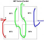
Something I've been wondering about for some time now is what the ideal arrangement for a four battery series-parallel arrangement is. Many of the larger military vehicles use four 12v batteries arranged in a series parallel arrangement and have both 12 and 24v systems in the vehicle.
A simple parallel arrangement -
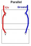
Though this may be an oversimplification in order to get my point across, consider the following circumstance - You're using the above arrangement in a vehicle (such as a modern diesel pickup truck with two batteries) and you're using an accessory that is drawing 30 amps of 12v power from the system. You would expect that you're basically getting 15 amps from one battery and 15 amps from the other. However, because of the internal resistances of the batteries themselves, the resistance of the wiring and the terminal connectors, due to the electrical proximity, and maybe other concerns, more current is drawn from the top battery than the bottom battery. When the alternator charges this setup, the same problem occurs - the top battery is charged more than the bottom. This problem is compounded with additional batteries. If you had a bank of 4 or 6 batteries arranged in this "ladder" style, you could continually cause imbalance issues with the "far" batteries.
In many cases, what I'm describing can be a problem that doesn't actually have a lot of real world effect, depending on the application, but it is also very easy to counteract by arranging the batteries like this -

This arrangement allows for a much better sharing of current use and correct charging and is not terribly difficult to achieve in most setups.
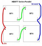
So now let us examine a common series-parallel arrangement, like the M939, M915, FMTV, HET, etc...
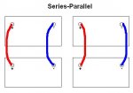
We take four 12v batteries and make two banks of two batteries in a parallel arrangement.
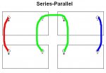
Then we add another wire to complete the series-parallel circuit, hooking the two parallel banks into series with each other.
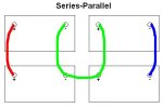
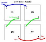
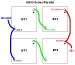
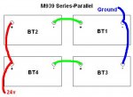
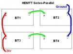
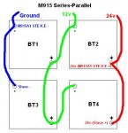
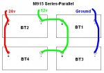
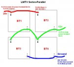
There are several places that wire could be...
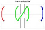
Something I do not know is if there is a preferred arrangement between the two shown above. I know all will work, but I would imagine that one is superior in some way.
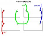
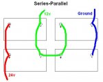
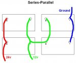
And where you grab the 12v from probably has an effect as well. Again, though all of these will work, there is probably a superior arrangement to be made here - and this is the information I am seeking. Anybody have any input?
It could very well be that factors like heat, age, quality of batteries, frequency of use, and other things contribute to a greater amount of "x factor" than ideal wiring arrangement, but I like getting things as close to perfect as I can, especially when it doesn't cost me anything.
A simple parallel arrangement -

Though this may be an oversimplification in order to get my point across, consider the following circumstance - You're using the above arrangement in a vehicle (such as a modern diesel pickup truck with two batteries) and you're using an accessory that is drawing 30 amps of 12v power from the system. You would expect that you're basically getting 15 amps from one battery and 15 amps from the other. However, because of the internal resistances of the batteries themselves, the resistance of the wiring and the terminal connectors, due to the electrical proximity, and maybe other concerns, more current is drawn from the top battery than the bottom battery. When the alternator charges this setup, the same problem occurs - the top battery is charged more than the bottom. This problem is compounded with additional batteries. If you had a bank of 4 or 6 batteries arranged in this "ladder" style, you could continually cause imbalance issues with the "far" batteries.
In many cases, what I'm describing can be a problem that doesn't actually have a lot of real world effect, depending on the application, but it is also very easy to counteract by arranging the batteries like this -

This arrangement allows for a much better sharing of current use and correct charging and is not terribly difficult to achieve in most setups.
So now let us examine a common series-parallel arrangement, like the M939, M915, FMTV, HET, etc...

We take four 12v batteries and make two banks of two batteries in a parallel arrangement.

Then we add another wire to complete the series-parallel circuit, hooking the two parallel banks into series with each other.

There are several places that wire could be...

Something I do not know is if there is a preferred arrangement between the two shown above. I know all will work, but I would imagine that one is superior in some way.


And where you grab the 12v from probably has an effect as well. Again, though all of these will work, there is probably a superior arrangement to be made here - and this is the information I am seeking. Anybody have any input?
It could very well be that factors like heat, age, quality of batteries, frequency of use, and other things contribute to a greater amount of "x factor" than ideal wiring arrangement, but I like getting things as close to perfect as I can, especially when it doesn't cost me anything.
Last edited:


