• Steel Soldiers now has a few new forums, read more about it at: New Munitions Forums!

  • Microsoft MSN, Live, Hotmail, Outlook email users may not be receiving emails. We are working to resolve this issue. Please add support@steelsoldiers.com to your trusted contacts.

Jumping in with both feet

gump65

New member
15
23
3
Location
Oro-Medonte, Ontario, Canada
Hello all!

Recently new here on SS with my first purchase and have started into a remove and replacement of the genhead on an 803A- it was known to be bad at time of purchase.
LID supplied me with all of the parts I need to be successful in my work - Shout out to LID!

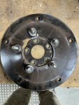
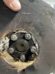
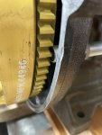
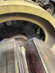
I have been documenting my progress with pictures which for most would be routine. When I came across the failed drive disc, this I thought some might find interest in. During running operation it was noted that sparks were being produced from the area around the starter. Thinking others could use this as a history note for diagnosis on similarly troubles gens.
With the outer stator removed the rotor is very unstable where it is fixed to the drive disc.

Will add more pics as I get the Rotor assembly clear.

Andrew


IMG_6772.JPG
 

pclausen

Well-known member
Steel Soldiers Supporter
452
281
63
Location
Afton, VA
Wonder if there was/is some sort of imbalance issue? Would probably be a really good idea to replace the rotor bearing as well. That drive disc is pretty stout, so I'm very surprised to see it fail like that. How many hours on that set?
 

Light in the Dark

Well-known member
Steel Soldiers Supporter
3,860
6,074
113
Location
MA
Glad to assist in helping you dive into the MEP world Andrew. I am also glad you are documenting this repair for future folks looking to do the same. @kloppk was kind enough to help me diagnose this set in person, before it took a drive to Oro-Medonte. I have no doubts your low hour machine will be making power before you know it.
 

Light in the Dark

Well-known member
Steel Soldiers Supporter
3,860
6,074
113
Location
MA
Wonder if there was/is some sort of imbalance issue? Would probably be a really good idea to replace the rotor bearing as well. That drive disc is pretty stout, so I'm very surprised to see it fail like that. How many hours on that set?
He got a NIB 10K genhead with his machine. Under 100 original hours.
 

Ray70

Well-known member
Steel Soldiers Supporter
2,633
6,057
113
Location
West greenwich/RI
Only other thing I could imagine is if the generator was not assembled correctly originally, like if the endcap and stator or stator and bellhousing weren't interlocked correctly ( where you have the lip that centers the stator ) causing everything to sit crooked ?
 

gump65

New member
15
23
3
Location
Oro-Medonte, Ontario, Canada
I will compare bearing cat #'s on the 2 rotor assemblies that I have. Hopefully they are a different number.
Guyfang, any idea of the replacement bearing number? Where would I search to get such a number?.......
 

gump65

New member
15
23
3
Location
Oro-Medonte, Ontario, Canada
Ok, there was more then a minor crack in the drive disk.....

.IMG_6789.JPGIMG_6784.JPG

Guy, the info you listed in the -24P TM is perfect. I am hoping to take the bearings into a local Bearing supplier and source an equivalent there. As long as they aren't proprietary, things should work out.

I am hoping the back side of the bearing will have ledgible info as the exposed side numbers have rusted beyond what I can read. I've chalked them, rubbed them with paint ( removing the excess paint ), a black sharpie will sometimes raise the numbers when the excess is removed but also no luck.

I can only make out the identifiers on the 2 Bearing seals which are an SKF product. #06 119 and #06 186


Question regarding Torque values
I've been looking for the values for the rotor to drive plate and drive plate to flywheel bolts. No luck yet.
I found values in TM 253-24 Appendix E, pg 103 for flywheel to crankshaft.
 

gump65

New member
15
23
3
Location
Oro-Medonte, Ontario, Canada
Only other thing I could imagine is if the generator was not assembled correctly originally, like if the endcap and stator or stator and bellhousing weren't interlocked correctly ( where you have the lip that centers the stator ) causing everything to sit crooked ?
I did have in mind what you suggested but all seemed to be seated as they should when removed. In preperation for reassembly I have wired wheeled all mating surfaces to remove any spots that might give me some grief.
 

G744

Well-known member
Steel Soldiers Supporter
1,725
3,884
113
Location
Hidden Valley, Az
I've seen that same type of genset failure, caused by the armature pressing on the flex plate too hard.

It was the improper longitudinal location of the support bearing.

DG
 

gump65

New member
15
23
3
Location
Oro-Medonte, Ontario, Canada
I've seen that same type of genset failure, caused by the armature pressing on the flex plate too hard.

It was the improper longitudinal location of the support bearing.

DG
I've seen that same type of genset failure, caused by the armature pressing on the flex plate too hard.

It was the improper longitudinal location of the support bearing.

DG
Thanks DG for the information. Will certainly find out about how to ensure the support bearing is located correctly to a longitudinal dimension.
 

gump65

New member
15
23
3
Location
Oro-Medonte, Ontario, Canada
Moving on,
Found the torque numbers for the Flywheel
TM 9-2815-253-24, Table E-1, Flywheel Bolts 50.1,51.3, 52.5

Haven't found the torque values for drive plate to flywheel and rotor to drive plate numbers. Is anyone able to point me in the right direction?

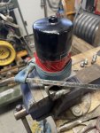
In the end I won the battle with removal of the fuel/water separator from the mounting bracket. Made a primitive rope wrench. Pic below
Used a 2' pry and she did not want to give up being seated there!!!!

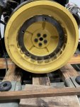
Next item. Having replaced flywheel, I want to ensure clearence between Rotational Transducer and Flywheel is set or at least checked. Imagine somewhere around >.010" would work? I haven't adjusted yet it since replacing Flywheel and it just looks tooooo close. Again haven't found the correct chart for these sorts of numbers and probably just not looking in the right spot....
TM 9-6115-642-24P page 34 Motional Transducer Assembly

IMG_6821.JPGIMG_6803.JPGIMG_6824.JPG


If I should start a new thread, I will copy this post to a new one.

As always thanks for any and all help!
 
Top
AdBlock Detected

We get it, advertisements are annoying!

Sure, ad-blocking software does a great job at blocking ads, but it also blocks useful features of our website like our supporting vendors. Their ads help keep Steel Soldiers going. Please consider disabling your ad blockers for the site. Thanks!

I've Disabled AdBlock
No Thanks