• Steel Soldiers now has a few new forums, read more about it at: New Munitions Forums!

  • Microsoft MSN, Live, Hotmail, Outlook email users may not be receiving emails. We are working to resolve this issue. Please add support@steelsoldiers.com to your trusted contacts.

LMTV '04 M1078A1 starting issues

MatthewWBailey

Well-known member
Steel Soldiers Supporter
885
1,619
93
Location
Mesa Colorado
Mine is pretty steady/consistent. Another thing to look for is AC component(ripple) on the DC lines.
This is what I'm getting today. The numbers are 13/25 during initial startup with AIH on full, then when AIH kicks off, the 14 leg climbs to 16 but is hovering above and below, I guess keeping the 3s timer from counting down and OVCO'ing. It settles a little to the numbers in the video. I tried disconnecting wire E in the reg on the fly but the 14v goes back to this high level. I'm wondering if the lack of lbcd capacitors is causing the abrupt AIH shutoff to percolate a transient that affects the regulator. Seems like nonsense but who knows.


hike

—realizing each day
Steel Soldiers Supporter
539
851
93
Location
Texas Hill Country
I am far, far from an expert and know a little bit beyond nothing on these vehicles, though years ago with our caterpillar tractors I would have said. "Okay, we are good," with the readings in your video.

I find as I wiggle the tester's lead on bolt heads, or try to ground on some grease/dirt/rust/paint the readings wiggle. To my shade tree head, your readings are good. I have never seen a perfect tractor in the field, yet we moved a lot of dirt–
 

Ronmar

Well-known member
3,913
7,586
113
Location
Port angeles wa
Those should be way steadier than that. One of 2 things is probably happening. Either the alternator regulator is not able to stabilize the voltage, possibly due to bad connections, or the load itself is unstable, possibly due to bad connections ect.

if you disconnect the exc lead from the regulator(forward screw terminal), or pull relay K11, the alt should stop generating power and that voltage should drop to battery voltage. Is that voltage stable With the truck running on batteries?

Another test would be to disconnect the alt from the truck, and connect it to a pair of batteries in series(ground, 12 and 24) separate from the truck, then start and run the engine on the installed batteries and see how the alt performs/stabilizes into the standalone batteries instead of the truck circuitry/load. You will have to apply 28V to the exc terminal on the reg from the battery set that is connected to the alternator ground point…

this alt regulates in 2 ways, like a traditional alt it monitors 28V and modulates the field to maintain that voltage. It also modulates the SCRs between the primary and secondary windings like the output of a switching power supply, to create the 14v. I don’t necessarily see one being low/unstable and one being high and unstable as a problem with the truck side of the equation…
 

GeneralDisorder

Well-known member
Steel Soldiers Supporter
2,101
5,360
113
Location
Portland, OR
These alternators have a lot of ripple. Niehoff considers it normal and it's an effect of the slow brushless response.

15v-16v is too high. But the fluctuation is normal - really need an oscilloscope. DVOM is not a great tool for this job. Even an analog meter is better that that digital mess that gives you no real data just a really nice seizure inducing headache.

That said - I don't typically read that kind of fluctuation with my DVOM. But maybe I'm using a different setting or mine is a slower response.
 

Ronmar

Well-known member
3,913
7,586
113
Location
Port angeles wa
Well I mentioned it earlier, if you set your meter for AC, it will read the ripple as an AC voltage. It is a little easier to quantify it that way, and actually assign a voltage closer to the peak of the excursions that the display cycling, is probably not catching. Thats a decent meter he is using in his video, I use a Fluke 87, and mine is nowhere near that unstable.
 

GeneralDisorder

Well-known member
Steel Soldiers Supporter
2,101
5,360
113
Location
Portland, OR
My primary meter is the Agilent (HP) U1252A which is what the military uses in the SWICE kits and I don't see fluctuations like that on normal DC voltage settings. Fluke may be faster I'm not sure - but I am using a $600 meter (the newest version being the 1252B which is $650)....... I would think it on par with the Fluke.
 

MatthewWBailey

Well-known member
Steel Soldiers Supporter
885
1,619
93
Location
Mesa Colorado
Those should be way steadier than that. One of 2 things is probably happening. Either the alternator regulator is not able to stabilize the voltage, possibly due to bad connections, or the load itself is unstable, possibly due to bad connections ect.

if you disconnect the exc lead from the regulator(forward screw terminal), or pull relay K11, the alt should stop generating power and that voltage should drop to battery voltage. Is that voltage stable With the truck running on batteries?

Another test would be to disconnect the alt from the truck, and connect it to a pair of batteries in series(ground, 12 and 24) separate from the truck, then start and run the engine on the installed batteries and see how the alt performs/stabilizes into the standalone batteries instead of the truck circuitry/load. You will have to apply 28V to the exc terminal on the reg from the battery set that is connected to the alternator ground point…

this alt regulates in 2 ways, like a traditional alt it monitors 28V and modulates the field to maintain that voltage. It also modulates the SCRs between the primary and secondary windings like the output of a switching power supply, to create the 14v. I don’t necessarily see one being low/unstable and one being high and unstable as a problem with the truck side of the equation…
Answer to 2nd paragraph question is yes. The meter was reading 13.5-6 and flat, high side was 25.6 but flat. The amp reading going to the 24v+ battery is all over the place with The alt energized, goes from 0-13ish and everywhere in between. Maybe I got some internal alt issues. I'm wondering if this alt shamed the other regulator. I still have that original one. I might try it to see if it's actually bad but I was never able to get it to reset. The voltage when the ovco trips is very flat also. With 4 batteries it Runs 24 slowly down to 23.7 over a few minutes that's with the AIH already off.

These 787 meters are all I have at present. I did a lot of PLC work on the last project at the black hole, big chiller system. These were great for sourcing 4-20ma. I had 2 really nice fluke scopemeters once but those got consumed by my divorce, along with lots of other great things.

A scope would be nice. The AC setting on most dmms is ok but is tuned for rms on sine waveforms so may be quirky with dirty waveforms . I could use average DC on these 787s because they have recording.
I'm going to slap my megger on some of these big leads with the alt disconnected. I have a 10A biddle which is great for low voltage busses.
 

Ronmar

Well-known member
3,913
7,586
113
Location
Port angeles wa
Mine varies about .05V from 28.56 to 28.61 measured with a fluke 87 at the alt this morning. AC showed ~.4V of ripple...

That is up from last year, and it has typically been ~28.2V, so i may have something going on there. The 14v is still right around 14.1 on the dash, but didnt put the fluke on that output this morning... i sample 14 and 28 at the alt output for the dash voltmeters...
 

MatthewWBailey

Well-known member
Steel Soldiers Supporter
885
1,619
93
Location
Mesa Colorado
I've confirmed today that my old VR is a dead duck. I put it on there and it did nothing. As my dad would say, "It's shot". Plugged the existing one back in and did some more observation. The AC value is running 174hz at idle with a little ripple. Note for future tach install?: If the engine idle setting is 650rpm, then this Hz value calculates to 16x the engine speed. I'm assuming this can be inputted directly to any electronic tach since it measures as a 14.5v signal max? Seems pretty usable for that purpose now that LBCD has no use for that wire.

the 14v leg is still high and spikes over 16 when the AIH turns off even while the high leg only goes from 24 to 28. The amps on the Alt ground strap are all over the place too but when E is disconnected those amps setttle to 4.5ish and flat. See videos.

So, Assuming it takes the field a few minutes to fall away and the alt is still producing when E is immediately disconnected, AND there's no amp variation during this time, the conclusion is a bad VR. No? I'm having trouble finding a meaningfully poor wiring issue. The ground strap seemed overly painted on the frame but no change after grinding it off. The other leads on the batt neg and frame were clean.

My other issue pointing to the VR is that the 28v high leg is steady. So the vr is having trouble regulating that 14v center point between the batteries and if the current flow is that irregular, something must be amiss in either the vr or the alt itself. I've never seen DC amps fluctuate that wildly when nothing big is on. It's rock solid when E is disconnected.


MatthewWBailey

Well-known member
Steel Soldiers Supporter
885
1,619
93
Location
Mesa Colorado
Have you gone through the troubleshooting manual and done the tests on the alternator itself?

Your ECM has a dedicated tach driver output so using the alternator VR is not necessary.
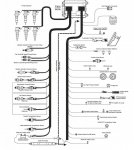
I've not done the 2.2ohm test yet. But per chart4, I'm already at bad alt, since I'm already working with a new reg, except that it's not a "known good reg". So this is not definitive. I'll do chart 2 and 3 tomorrow. I effectively did chart 1 and 4 already with no real answers. Those EMP people have cursed me!!

on the tach, I didn't know the ECM had that. Didn't see it in the online wiring schematics. I see tachs in some of the A0 pictures, so wasn't sure if it was same on my A1. Is that a terminal that's in the PDP? I just bought a nice Isspro 3k tach so I'm looking for ways to drive it aside from the crude wrap around pickup they provide.
 

Attachments

hike

—realizing each day
Steel Soldiers Supporter
539
851
93
Location
Texas Hill Country
Cat ECM pinout does show the tachometer feed on the OEM side, though I have yet to find it in the schematics. It does read in the J1939 feed to diagnostics.

CAT-3126-ecu-pinout.jpg

I keep wondering if it is in the connector under the windshield 'behind' the heater in all units, like in A0 units; and running off the ring gear in all A0, A1, and A1R units. Who has seen different factory tachometers between different flavored units?
 

Attachments

GeneralDisorder

Well-known member
Steel Soldiers Supporter
2,101
5,360
113
Location
Portland, OR
on the tach, I didn't know the ECM had that. Didn't see it in the online wiring schematics. I see tachs in some of the A0 pictures, so wasn't sure if it was same on my A1. Is that a terminal that's in the PDP? I just bought a nice Isspro 3k tach so I'm looking for ways to drive it aside from the crude wrap around pickup they provide.
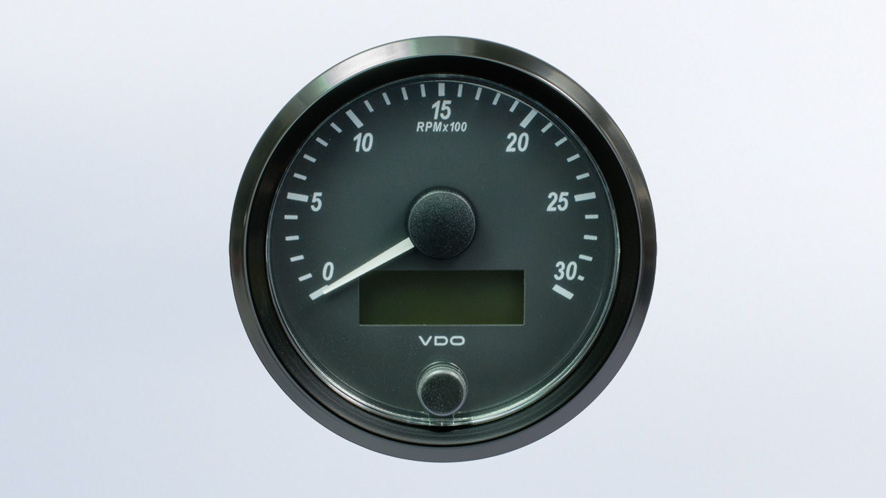
I would just get a J1939 tach. Such as:


Ronmar

Well-known member
3,913
7,586
113
Location
Port angeles wa
Cat ECM pinout does show the tachometer feed on the OEM side, though I have yet to find it in the schematics. It does read in the J1939 feed to diagnostics.

View attachment 916487

I keep wondering if it is in the connector under the windshield 'behind' the heater in all units, like in A0 units; and running off the ring gear in all A0, A1, and A1R units. Who has seen different factory tachometers between different flavored units?
The mil manuals/schematics don’t show the engine side of the ECU wiring on the 3126/c7 trucks…
 
Top
AdBlock Detected

We get it, advertisements are annoying!

Sure, ad-blocking software does a great job at blocking ads, but it also blocks useful features of our website like our supporting vendors. Their ads help keep Steel Soldiers going. Please consider disabling your ad blockers for the site. Thanks!

I've Disabled AdBlock
No Thanks