• Steel Soldiers now has a few new forums, read more about it at: New Munitions Forums!

  • Microsoft MSN, Live, Hotmail, Outlook email users may not be receiving emails. We are working to resolve this issue. Please add support@steelsoldiers.com to your trusted contacts.

LMTV '04 M1078A1 starting issues

hike

—realizing each day
Steel Soldiers Supporter
531
838
93
Location
Texas Hill Country
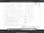
These pages show the CAT installed side (¿connector P1?) all in one place, the OEM side is liberally distributed about the other pages. It would be nice to find a pinout of the other connector, (¿P2 connector?).

I still think the OEM tach was always run off the ring gear.

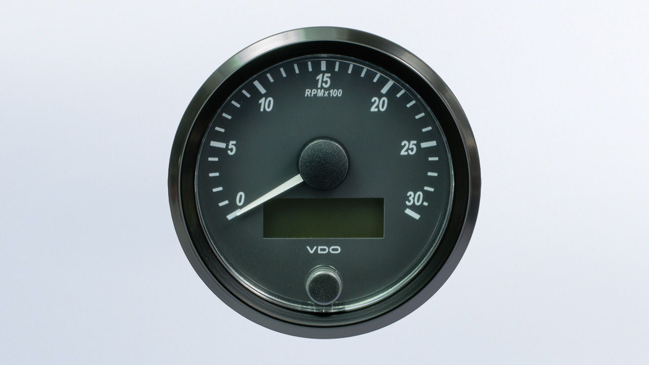
Though the VDO SingleViu gauges look like a good solution, too—
 

GeneralDisorder

Well-known member
Steel Soldiers Supporter
2,034
5,224
113
Location
Portland, OR
These pages show the CAT installed side (¿connector P1?) all in one place, the OEM side is liberally distributed about the other pages. It would be nice to find a pinout of the other connector, (¿P2 connector?).

I still think the OEM tach was always run off the ring gear.

Though the VDO SingleViu gauges look like a good solution, too—
The A1+ trucks don't have any provision for a tach except the J1939. The dedicated tach output from the ECM is not pinned much like the cruise control is not pinned. Since these trucks have no hand throttle they have no need of a tach. The A1+ winch trucks don't have the tach they just have a fast idle switch that puts the engine at a pre-determined PTO speed.

And the schematics do show all the ECM connections in one place - although the quality of some of the schematics kinda sucks. I can get better ones for the C7 but they're on a different computer at the moment....

1242393912a_large.jpg
 

MatthewWBailey

Thanks for this site. My truck runs great now!
Steel Soldiers Supporter
835
1,519
93
Location
Mesa Colorado
I would just get a J1939 tach. Such as:

I already bought the Isspro. Can that be driven off the bell housing pickup in parallel with its signal to the ECM?
 

GeneralDisorder

Well-known member
Steel Soldiers Supporter
2,034
5,224
113
Location
Portland, OR
I already bought the Isspro. Can that be driven off the bell housing pickup in parallel with its signal to the ECM?
The A1+ trucks don't have a bell-housing pickup. The ECM is generating the RPM internally using the top and bottom camshaft timing sensors. Your choices are to pin the ECM chassis connector to get the dedicated tach drive much like we do to gain access to the cruise control functions, or use the J1939.
 

MatthewWBailey

Thanks for this site. My truck runs great now!
Steel Soldiers Supporter
835
1,519
93
Location
Mesa Colorado
Again, thanks you guys for all the wisdom and conversation. This is a lot of fun and even though it's a been a tedious alternator problem, it's a blast to work on this stuff. Reminds me of motors-lab in college. I just read papers and code books at work so this is a real fun diversion.

now, back to hell: I ran thru the neihoff T-shooting guide in full. Chart 2 and 3 also passed, leading to "replace with known good regulator", which I can't do. 2.2 ohms in chart 2 passed. As did chart 3's stuff. I get that these TM guides are just basic and not comprehensive.

my educated guess is that the 14v part of the reg is faulty. To save from any over voltage damage on 14v side, I'm just pulling the leads on the alt and running a battery only truck for the time being. I see that the 14v leg goes into the ECM so last thing I need is to blow that up. With the alt disconnected, truck starts and runs at 25.8/13.02 steady and the batt amps are flat. I realized that you'll always see amps on the alt ground strap regardless of alt on or off since it's one of 2 parallel grounds to the engine frame, so current divider. I'm getting 4.5 amps on one and 4.5 amps on the other using battery only.

I'll figure out the pulley compatibility then work on swapping in that 24v Cat alternator. Can't afford any more neihoff regulators. Should be a fun project. My experience reminds me I've literally never bought a used truck in 30yrs where I did not have to replace the alternator, batteries, brakes, and tires. Although the brakes on this look new.
 

MatthewWBailey

Thanks for this site. My truck runs great now!
Steel Soldiers Supporter
835
1,519
93
Location
Mesa Colorado
The A1+ trucks don't have a bell-housing pickup. The ECM is generating the RPM internally using the top and bottom camshaft timing sensors. Your choices are to pin the ECM chassis connector to get the dedicated tach drive much like we do to gain access to the cruise control functions, or use the J1939.
I'll coordinate with you via PM
 

GeneralDisorder

Well-known member
Steel Soldiers Supporter
2,034
5,224
113
Location
Portland, OR
To save from any over voltage damage on 14v side, I'm just pulling the leads on the alt and running a battery only truck for the time being. I see that the 14v leg goes into the ECM so last thing I need is to blow that up. With the alt disconnected, truck starts and runs at 25.8/13.02 steady and the batt amps are flat.
Engine ECM uses 24v exclusively from my experience. Although it will happily run on anything down to about 10v. At 28v it draws about 1.2A with the engine running.

Only computer I'm aware of that runs on 14v is the ABS unit.
 

MatthewWBailey

Thanks for this site. My truck runs great now!
Steel Soldiers Supporter
835
1,519
93
Location
Mesa Colorado
Engine ECM uses 24v exclusively from my experience. Although it will happily run on anything down to about 10v. At 28v it draws about 1.2A with the engine running.

Only computer I'm aware of that runs on 14v is the ABS unit.
Curiously, my ABS is not working, at least not when I did a little downhill snow test in the driveway.
 

hike

—realizing each day
Steel Soldiers Supporter
531
838
93
Location
Texas Hill Country
We are saying the essentially the same thing, except notice that only one connection is at P2, the rest are to P188. It would be nice to see the P2 pinout—

IMG_3294.png
 

Lostchain

Well-known member
Steel Soldiers Supporter
285
587
93
Location
Portland, OR
my educated guess is that the 14v part of the reg is faulty. To save from any over voltage damage on 14v side, I'm just pulling the leads on the alt and running a battery only truck for the time being.

Previous to cleaning the regulator to alternator connection, weren't you getting OVCO on the 28V side? Now that problem has migrated to the 14V side?

You deleted 2 of your 4 batteries right? I wonder what would happen if you completely removed the alternator from the truck wiring, and cabled it directly to the other 2 batteries with jumper cables. Essentially bench testing the system removing almost all of the variables...
 

MatthewWBailey

Thanks for this site. My truck runs great now!
Steel Soldiers Supporter
835
1,519
93
Location
Mesa Colorado
Previous to cleaning the regulator to alternator connection, weren't you getting OVCO on the 28V side? Now that problem has migrated to the 14V side?

You deleted 2 of your 4 batteries right? I wonder what would happen if you completely removed the alternator from the truck wiring, and cabled it directly to the other 2 batteries with jumper cables. Essentially bench testing the system removing almost all of the variables...
It was floating a lot on 28 but never went any higher than 30. All that time I never had a high 14 leg. It settled during that long trip to 28ish with no floating and the 14v was 14 during that trip. I put the 4 batteries back in for that trip as a precaution since the lbcd was removed. The 14v ovco started the day after that. It too, settles the longer the truck runs, but only down to 15.25. Basically, now, if the AIH runs bc it's cold, the 14v leg goes >16 as soon as AIH shuts off while the high leg goes to 28 and stays there. Aggravating as all heck since not one of the TM troubleshooting guides flowcharts to a fail.

I could easily check with 2 other batteries out of the truck to see the reactions. I have some other 12 AGMs sitting around that are new 100ah VRLA's. Pretty easy check Ill try tomorrow 👍.
 

MatthewWBailey

Thanks for this site. My truck runs great now!
Steel Soldiers Supporter
835
1,519
93
Location
Mesa Colorado
If the batteries are charged and in good shape, it shouldn’t matter 2 or 4… Thats the point of the regulator:)
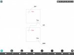
I'm wondering what you think of this. You may have covered this in another thread previously. But after doing some node analysis, I realized that with a dual volt alt, you can never have equal current thru both batts. See pics. i2 is never equal to i7, although they could be "close" in certain circumstances. Seems to me the designers kinda put blinders on since the 14v SCR switched output only bolsters the bottom battery, while the top is left to float between that voltage and the 28 output of the rectifier. The 28v supply's current always flows thru both batts but the 14v only flows thru one, creating a natural problem of imbalance. On mine, I think this is reflecting/promoting an out of balance battery pair, exacerbating the 14v ovco. I know @GeneralDisorder has stated flipping batts on dozens of posts. I'm not aware of such imbalance on straight 24v series batt pairs. Is that a thing? Do 24v series batt sets show imbalance over time?

I'm wondering if I can solve my 14v ovco by either simply flipping batts or by only running 28v on this neihoff and lifting the 14v center lead to the batts, eliminating the 14v lead from the alt altogether. (Of course then adding a power supply in the PDP to feed 12v loads and converting one pack of batts to 12v parallel).

Looking at these node formulas, I scratch my head on why the designers introduced an unnecessary problem. Maybe the vr manages it in optimum conditions and then starts failing on the 14v first? I've always noticed my 14v voltmeter is way high during starting, then drops during AIH, then goes back up after AIH. Hard to hold a center reference voltage when the controls only act in one direction.
 

Attachments

GeneralDisorder

Well-known member
Steel Soldiers Supporter
2,034
5,224
113
Location
Portland, OR
Tell me more about this high 14v reading during starting? Maybe a video of what you are reading.......

AIH runs on 28v and on my truck I do see the 28v side drop when the AIH is in play. One of the first problems I fixed with my truck was that some PVT Snuffy type had connected the AIH to the 14v lug on the LBCD.

Gauges should read pretty close to 12v and 24.5v with ignition on and engine off.
 

Ronmar

Well-known member
3,846
7,476
113
Location
Port angeles wa
Please tell me more about the 3rd pic, the altered battery box diagram… yours isn’t wired like this is it?

What I have observed playing with my 100A Neihoff is that it is configured as a battery balancer. It is looking for a 12v connection INTO THE MIDDLE of a 24v series battery string. When it does not see that connection, mine does not operate properly… as I recall it pulsed/cycled looking for that relationship, because any change on a voltage fed to the 12 or 24v point in a series string will effect the other voltage. When it does not see this interaction it resets. As I recall it also derated the 28v output. Let me see if I can dig up where I wrote about it, was a long while back…

if yours are wired like that altered diagram, you have 1. Removed that 12 from the middle of 24. 2. Created two vastly different size battery banks(24v@120AH, and 12V@240AH), that would be impossible to balance anyway, even if they were connected in a fashion that satisfied need number 1.

if wired like that, I would not expect a dual volt Neihoff to operate properly…

if you are wired like that, a quick check would be to disconnect the red lead in the drawing where it connects to BT4+, and connect it to either BT3+ or BT1-. That would connect the 12v alt output to the middle of 2 equal size batteries in series as Neihoff designed it…

whatever the size of your batteries, it should be wired like this and ONLY like this…

IMG_3212.jpeg
 

MatthewWBailey

Thanks for this site. My truck runs great now!
Steel Soldiers Supporter
835
1,519
93
Location
Mesa Colorado
Please tell me more about the 3rd pic, the altered battery box diagram… yours isn’t wired like this is it?

What I have observed playing with my 100A Neihoff is that it is configured as a battery balancer. It is looking for a 12v connection INTO THE MIDDLE of a 24v series battery string. When it does not see that connection, mine does not operate properly… as I recall it pulsed/cycled looking for that relationship, because any change on a voltage fed to the 12 or 24v point in a series string will effect the other voltage. When it does not see this interaction it resets. As I recall it also derated the 28v output. Let me see if I can dig up where I wrote about it, was a long while back…

if yours are wired like that altered diagram, you have 1. Removed that 12 from the middle of 24. 2. Created two vastly different size battery banks(24v@120AH, and 12V@240AH), that would be impossible to balance anyway, even if they were connected in a fashion that satisfied need number 1.

if wired like that, I would not expect a dual volt Neihoff to operate properly…

if you are wired like that, a quick check would be to disconnect the red lead in the drawing where it connects to BT4+, and connect it to either BT3+ or BT1-. That would connect the 12v alt output to the middle of 2 equal size batteries in series as Neihoff designed it…

whatever the size of your batteries, it should be wired like this and ONLY like this…

View attachment 916789
No the 3rd pic is a draft of what I may do if I convert to a 24v only alt with victrons making 12v within the PDP. It only needs to be one battery but I made the drawing anyway. Sorry, didn't mean to confuse that.

I wasn't sure if the 100a neihoff would operate
As 24v only. I think you said earlier that requires a different reg but I was curious since mine is running 14ovco but fine at 28. Im just trying to avoid another machine shop project swapping in my 150a cat alternator. I am committed on finalizing my v plow creation which has priority over all my shop equipment at the moment.

when I get ideas, things usually go up in smoke, but can the 14v side be tricked out by an external 14v voltage supply? Or does current have to flow thru that 14v terminal? (As a kid, I once used a glass saw to cut off the bulb glass on a 100w incandescent just to "see what happens". Of course it lit up like the sun once plugged in but only a for few seconds :). So that's why I like to get more eyes on my "ideas".)
 

MatthewWBailey

Thanks for this site. My truck runs great now!
Steel Soldiers Supporter
835
1,519
93
Location
Mesa Colorado
Tell me more about this high 14v reading during starting? Maybe a video of what you are reading.......

AIH runs on 28v and on my truck I do see the 28v side drop when the AIH is in play. One of the first problems I fixed with my truck was that some PVT Snuffy type had connected the AIH to the 14v lug on the LBCD.

Gauges should read pretty close to 12v and 24.5v with ignition on and engine off.
Yes on the numbers with ign on and engine off. The truck is sitting there now like that bc I have the alt disconnectedboth power leads open and E is open.

the 14v value is odd at and after startup. Ill do another video off it. Seems like the vr balancing is moving around. During AIH, it goes up from the start sequence value, then slowly but steadily drops to 13ish, the spikes to 16+ upon AIH dropout. That's with alt connected.

I haven't tried the external battery test yet but i don't expect much change. The leads to the batts ring out low impedance and the truck starts and runs perfect with only the 4 batteries in there, no alt. (Lbcd gone, leads bolted together). So now, AIH drops the volts from 24 to 22 but then AIH drops out and volts bounce up to 23ish slowly. Voltmeter is slow and uneventful as expected. So if there's a connection Issue, it's not affecting the battery only arrangement I have. I've been charging it up at night lol. Either need a bed full of batteries or fix this neihoff. It seems like a meaty, bulletproof piece of copper and steel, way more robust looking than the cots Cat alternator. I don't get it.
 
Top