• Steel Soldiers now has a few new forums, read more about it at: New Munitions Forums!

  • Microsoft MSN, Live, Hotmail, Outlook email users may not be receiving emails. We are working to resolve this issue. Please add support@steelsoldiers.com to your trusted contacts.

LMTV M1078 Wont start.

Issati

Member
31
12
8
Location
94131
2 more questions,
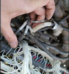
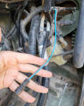
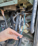
1. There are some unplugged cables on the passenger side, does anyone know where these go??
T3.png T4.png t5.png

The blue and green cable on the left two pictures? how about the P99, PX50 and PX34 on the right picture.


2. Can you please watch the following video that I posted to YouTube and let me know what is going on with this??


Thank you so much for all the help, You guys rock!
 

Ronmar

Well-known member
3,827
7,431
113
Location
Port angeles wa
The blue brown wires are for the fan control solenoid. That plug connects to PX34...

In your video that is the CTIS pressure control unit(PCU). The little part jiggling is the deflate pressure regulator/relief valve.

PCU basics: it has 3 solenoid valves 2 closed 1 open, that relief/regulator and a pressure transducer. The open valve is the control valve. It vents the PCU manifold to the atmosphere so the CTIS controller closes it to do anything. The other two valves are supply and deflate. Supply opens to admit air from the wet tank protection valve To pressurize the system, open wheel valves and fill tires if commanded. Deflate opens/vents the PCU manifold to that 6PSI relief valve which drops the system pressure to 6-8 PSI. This is enough to keep the wheel valves open and shift the dump valves to the dump position as the greater pressure in the tires exits rapidly thru the dump valves. The transducer allows the controller to measures pressure in the manifold.

I recall you saying your CTIS controller is unplugged? If you are seeing this With the controller unplugged, well the supply solenoid is leaking as that air is coming from somewhere. The control solenoid should be open and venting any air to the outside thru a port in the floor. I would suspect that it is clogged, perhaps with a mud dauber/bee nest? And of course for air to be reaching that relief valve the dump solenoid is leaking.

my controller was bricked when I got my truck, I made it into a manual controller and operate the 3 PCU valves with buttons. Made this video to show how it works, which might give you a better idea how it is supposed to operate...


Issati

Member
31
12
8
Location
94131
Hello,
Okay so the front and rear glad hand covers look like these, is this not correct?

111.png<---Front Rear --->222.png
 

coachgeo

Well-known member
5,143
3,461
113
Location
North of Cincy OH
Hello,
Okay so the front and rear glad hand covers look like these, is this not correct?

<---Front Rear --->
it is the tail on these donkeys we need to see (the other side). The front ones on the other side should be markedly different than ones made for the rear. The vent on the military fronts will look something like the yellow part of the vents shown in below pic (just not yellow). Civilian version may just be a hole? Rear covers are just stamped solid metal.


PSMagGladHndVented.png
 
Last edited:

Issati

Member
31
12
8
Location
94131
Here are some more pictures of the front of the car.
Are these not correct?


40.png45.png41.png

I think I will be better-off buying new ones for the front as these look old.
any recommendation on where to buy some new ones?
 

Ronmar

Well-known member
3,827
7,431
113
Location
Port angeles wa
Yep, wrong covers on the front. Just leave them off until you get vented ones... you should also note how much air, if any is venting out those front glad-hand connections.

in a perfect world, it should be none, but check valves occasionally leak. If it is a lot, you will need to find the issues. Below the red emer gladhand behind the bumper is a check valve that feeds back to the wet tank. there is a T there and the red glad-hand also feeds a 2way check valve below the drivers floor(behind grill).

there are three 2way checkvalves mounted vertically in a row under the drivers floor(directly in/behind the drivers step). The red glad-hand feeds the top one with the pressure switch and The front blue service glad-hand feeds the other two 2way check Valves below it.
 

coachgeo

Well-known member
5,143
3,461
113
Location
North of Cincy OH
Here are some more pictures of the front of the car.
Are these not correct?


View attachment 820081

I think I will be better-off ... where to buy
still need to see the other side of the cover. In this pic. the edge of the cover at left corner shows what "might" be the vent portion on the back side of it..... but not enough of the image shows to identify that or not. Like Ron says..... till you get us a better picture to ID them for sure..... leave the caps off so they for sure vent.

where to buy... napa etc. See the sticky/pinned thread at top of this forum for part numbers (spread sheet)
 

Ronmar

Well-known member
3,827
7,431
113
Location
Port angeles wa
still need to see the other side of the cover. In this pic. the edge of the cover at left corner shows what "might" be the vent portion on the back side of it..... but not enough of the image shows to identify that or not. Like Ron says..... till you get us a better picture to ID them for sure..... leave the caps off so they for sure vent.

where to buy... napa etc. See the sticky/pinned thread at top of this forum for part numbers (spread sheet)
I don’t think that cover is vented, if vented, it would have a hole in the middle of the domed part of the cover, which is clearly visible, and it doesn’t...
 

tennmogger

Well-known member
Steel Soldiers Supporter
1,579
542
113
Location
Greenback, TN

Issati

Member
31
12
8
Location
94131
Okay so here is what I have so far,

I have 24V in CB21, the fuse is working correctly as well, however I have nothing in pin 86 of the starter relay (K1)
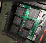
I have changed every single relay of the (neutral start contacts in the vehicle interface module(black plastic box under passenger dash)
Relays .png
It had 5 of 24V and one 12V as seen in the picture bellow, not sure if this is correct or not, I just replaced all with the same voltage.


To see if everything passed K1 is working correctly, I cut opened the relay of K1 and tried manually connecting the pins and it started the car, please see the video below.


I am not sure what to do as my next move,
Any Ideas will be much appreciated


Thank you
 

coachgeo

Well-known member
5,143
3,461
113
Location
North of Cincy OH
Okay so here is what I have so far,

I have 24V in CB21, the fuse is working correctly as well, however I have nothing in pin 86 of the starter relay (K1)
I have changed every single relay of the (neutral start contacts in the vehicle interface module(black plastic box under passenger dash)
View attachment 820723
It had 5 of 24V and one 12V as seen in the picture bellow, not sure if this is correct or not, I just replaced all with the same voltage.


To see if everything passed K1 is working correctly, I cut opened the relay of K1 and tried manually connecting the pins and it started the car, please see the video below.


I am not sure what to do as my next move,
Any Ideas will be much appreciated


Thank you
nothing to add but... great investigating...... keep it up
 

Ronmar

Well-known member
3,827
7,431
113
Location
Port angeles wa
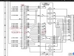
the start button provides a pathway to ground When pushed. That ground path passes thru the start lockout relay K24’s energized contacts. K24 energizes when the main switch is turned on and de-energizes when oil pressure goes over 15PSI To keep you from cranking a running engine.

the ground path from the closed contacts of K24 goes to pin 85 of relay K1.

The positive current to energize K1 starts at CB21. It goes thru the neutral start relay in the VIM then to pin 86 of K1.

so with the main switch on(trans display on), remove relay K1 and you should measure 24v to ground at the K1 socket, pin 86.(pin numbers are on relay).

when you turn on the main sw, K24 should energize. With a meter set for resistance, you should be able to measure a low resistance path to ground from K1 socket pin 85 when the start button is pushed...
 

Issati

Member
31
12
8
Location
94131
the start button provides a pathway to ground When pushed. That ground path passes thru the start lockout relay K24’s energized contacts. K24 energizes when the main switch is turned on and de-energizes when oil pressure goes over 15PSI To keep you from cranking a running engine.

the ground path from the closed contacts of K24 goes to pin 85 of relay K1.

The positive current to energize K1 starts at CB21. It goes thru the neutral start relay in the VIM then to pin 86 of K1.

so with the main switch on(trans display on), remove relay K1 and you should measure 24v to ground at the K1 socket, pin 86.(pin numbers are on relay).

when you turn on the main sw, K24 should energize. With a meter set for resistance, you should be able to measure a low resistance path to ground from K1 socket pin 85 when the start button is pushed...


I don't have any voltage on 86 of relay K1.
where is the neutral start relay in the VIM? And what does it mean if I have no voltage on Pin 86 of K1?
 

Ronmar

Well-known member
3,827
7,431
113
Location
Port angeles wa
I don't have any voltage on 86 of relay K1.
where is the neutral start relay in the VIM? And what does it mean if I have no voltage on Pin 86 of K1?
Don’t know which vim relay specifically but you can probably figure it out. I would start with pulling connector PX33 on the VIM and seeing if you have 24v on pin F1 Of the vehicle side connector. That comes from CB21 via TB1 pin 34.

since the VIM relays are the same as the other relays, you can use a ohm meter to try and find a circuit between F1 on the vim side of the PX33 connector to any of the pin30 or pin 87 relay socket locations In the VIM. Once you find it, check for a comparable circuit from the other relay socket(30 or 87) to G1 on PX33. once you find the relay, you can jumper it’s pin 30-87 to test the rest of the starter circuit.

But if the starter won’t spin with a relay in the socket, perhaps you have a trans controller issue that is failing to energize the neutral start relay...

Your vim is getting both 12 and 24v right(measure at the vim fuses)?


7554303C-81B4-41F4-8D27-7364130F1C34.jpeg
 

Issati

Member
31
12
8
Location
94131
Still haven't been able to start the car from the inside however when I manually start the car from the starter, My oil light stays on. any idea why that might be?
I have checked the engine and the Transmission oils and they are all filled to the correct dipstick specification.
can it be because of the transfer case having low oil? that is the only one I don't know how to check for.
 

coachgeo

Well-known member
5,143
3,461
113
Location
North of Cincy OH
Still haven't been able to start the car from the inside however when I manually start the car from the starter, My oil light stays on. any idea why that might be?
I have checked the engine and the Transmission oils and they are all filled to the correct dipstick specification.
can it be because of the transfer case having low oil? that is the only one I don't know how to check for.
tranny/transfer case share oil
 
Top