Now for the rest of the story:
After using our plaza Arduino CTIS ECU for a while we decided to swap in our Dana Spicer M939A2 CTIS ECU and reprogram it. The plaza unit is great and works fine we just want both units setup the same so to have a backup, and the Dana Spicer unit being push button is easier to operate while driving and offers less glare at night.
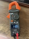
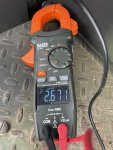
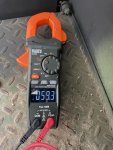
Upon installing the Dana ECU the ABS fault is back. Hooking up the diagnostics finds everything working, we can program the Dana unit, just the ABS fault is back. While testing the settings in the reprogrammed M939A2 ECU we smell that sweet burnt plastic smell. R12 and R13 are both fried.
After checking the schematics for the M1078A1 P110 plug at the CTIS ECU and comparing to the schematics for the M939A2 CTIS ECU it appears the M1078A1 and M939A2 wiring harnesses routed a few items differently at what appears to be the (M1078A1's P110) connector to the CTIS ECU.
Since
@GeneralDisorder has suggested the Dana Spicer ECU's do not connect across J1939 and we can connect to our Dana Spicer using J1708; I am thinking IF using the M939A2 CTIS ECU in our M1078A1 we need to disconnect 'G'.
note: The plaza Arduino CTIS ECU does not connect to the J1939 circuit at all, ('G', 'W', 'X').
M939A2 DIFFERENCES
1— no diagnostic connections listed;
2— speed signals routed through 'Y' and 'K';
3— pressure switch 'B' also used, routed through 'L';
4— additional ground routed through 'V';
5— 'a', 'N', 'U', 'M' and 'A' not used.
CONFLICTS
The M939A2 CTIS ECU uses — M1078A1 uses:
'G' for the Control Switch 'A' — the M1078A1 routes control switch 'A' to ground through 'F' and uses 'G' for J1939 (+);
note: if you follow the M1078A1 J1939 (+) wire it does connect to R13 and R12.
'M' for the Wrecker Only Ground — the M1078A1 routes ground through 'F' and uses 'M' for optional power;
Should be OKAY?
The M939A2 CTIS ECU uses — M1078A1 uses:
'W' for the Control Switch 'B' — the M1078A1 routes control switch 'B' to ground through 'F' and uses 'W' for J1939 (shield);
'b' for the Pressure Transducer 'A' — the M1078A1 routes pressure transducer 'A' to common through 'j' and uses 'b' for power;
'j' for the Pressure Transducer 'B' — the M1078A1 routes pressure transducer 'B' to power through 'b' and uses 'j' for common;
M939A2 schematic
View attachment 913437
M1078A1 <18500 schematic
View attachment 913438
As I fried the last of my 120ohm resistors I'll have to await the arrival replacements, next up: to see if disconnecting 'G' may allow using the M939A2 CTIS ECU in our M1078A1 unit without conflicting with the J1939 system and causing a fault in the ABS system.
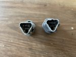
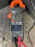
Thinking about how everything lines up and wishing to minimize changes to the M1078A1's wiring harness I decided to pull the 'G', 'W', and 'X' pins from the M939A2 CTIS ECU connector. Once I had pulled all three (matching the plaza Arduino CTIS, too) the ABS fault code dropped, and our diagnostics on both J1939 (not for CTIS) and J1708 all work. Once we receive new resistors we'll recheck the system voltages and ohms.
Being a rainy day here I took her out on a country road and tested the ABS system. Not sure I felt pluses in the pedal, though hammering the brakes at speed with nothing in the back didn't put us in a skid on a slick road. They are likely working or not yet needed.
Hopefully, isolating the M939 CTIS ECU from the J1939 system will be a longer term fix and keep the M939A2 CTIS ECU system conflict free on our M1078A1—


