• Steel Soldiers now has a few new forums, read more about it at: New Munitions Forums!

  • Microsoft MSN, Live, Hotmail, Outlook email users may not be receiving emails. We are working to resolve this issue. Please add support@steelsoldiers.com to your trusted contacts.

Looking for V100 chassis pics

Rooper90

New member
6
11
3
Location
Liberec Czech Republic
Hello!

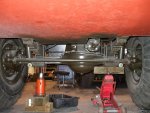
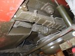
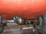
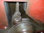
I'm looking for the best possible photos of the lower part of the V-100 Commando hull, preferably around the front and rear axles.
I'm a modeller and I'd like to build the most faithful replica of the V-100 in 1/35th scale. I have the Hobby Boss XM706E2 kit but unfortunately the lower part of the hull is completely wrong and doesn't match the real machine.
I already have a few photos of the lower part, but unfortunately I'm still not able to faithfully capture the quite complex V-100 "chassis."
Thank you very much for any help.
PS: If it doesn't belong in this forum, please forgive me.

George K.
 

M813rc

Well-known member
Steel Soldiers Supporter
4,236
3,321
113
Location
Near Austin, Texas
I have a 1/1 scale V100 which I did this thread on as I restored it -

https://www.steelsoldiers.com/threads/new-v-100.23235/

There are a lot of detailed pictures there for you to look at, particularly of the interior, which is totally inaccurate in the Hobby Boss kit. They based their interior on a V150 or V200, which differ inside quite a bit.
I took a lot of pictures as I went along, most of which are not in the thread. So if there are specific details you want to see, let me know.

Being a modeller myself, I will in turn want to see what you build!

A word of caution - do not use the popular flattened tires on a V100, that is inaccurate.
Due to the very stiff sidewalls, the tires do not sag at all, and look oddly round on the real vehicle because of that. The operators manual even states that you cannot tell if a tire is totally deflated by looking at it. ;)

I'll dig up some photos of the hull underneath for you shortly. It is mostly just flat as there is no chassis, per se. The axles are mounted directly to the hull in recesses.

Cheers
 

Rooper90

New member
6
11
3
Location
Liberec Czech Republic
I have a 1/1 scale V100 which I did this thread on as I restored it -

https://www.steelsoldiers.com/threads/new-v-100.23235/

There are a lot of detailed pictures there for you to look at, particularly of the interior, which is totally inaccurate in the Hobby Boss kit. They based their interior on a V150 or V200, which differ inside quite a bit.
I took a lot of pictures as I went along, most of which are not in the thread. So if there are specific details you want to see, let me know.

Being a modeller myself, I will in turn want to see what you build!

A word of caution - do not use the popular flattened tires on a V100, that is inaccurate.
Due to the very stiff sidewalls, the tires do not sag at all, and look oddly round on the real vehicle because of that. The operators manual even states that you cannot tell if a tire is totally deflated by looking at it. ;)

I'll dig up some photos of the hull underneath for you shortly. It is mostly just flat as there is no chassis, per se. The axles are mounted directly to the hull in recesses.

Cheers
Thank you for answer!

That's interesting information for me about tires. I have resin wheels from DEF Models, which I consider to be the best on the market. Unfortunately, they're in a loaded condition that you can't do much with.

The next thing I'm trying to figure out is which axles were used on the V-100, 2.5 ton axles from the M35 or 5 ton from the M54 series???
And for every photo of the bottom hull I will be very happy.

So far, I'm in the process of getting photos that I'll have to re-make the bottom of the hull from plastic plates. Unfortunately, I don't have a single dimension to navigate by. And I don't have a V-100 1/1 in my neighborhood, and I suspect there won't be a single piece in all of Europe either :D
 

M813rc

Well-known member
Steel Soldiers Supporter
4,236
3,321
113
Location
Near Austin, Texas
Hey, no worries SW! Your first choice (sniff sniff...no, no I'm perfectly fine..) may have better under-hull pictures, he has dealt with more Vs than I can even dream of playing with. ;)

I took a look at the Hobby Boss lower hull (I bought the kit when it first came out and never got around to building it) and it is pretty far off from the V100!
The top hull section and the details are all very good, but that lower hull piece is for a V150

The openings under the V100 should be just big enough to go around the axles, and where the driveshafts go up into the hull.
The rounded outer opening for the wheel wells are accurate, but the wheel wells themselves should be done in flat sections rather than rounded. The very early Vs had squared outer openings but it was found that hull cracks propagated from the corners, so they were rounded and that solved the problem.

The rear shocks sit in cutouts in the rear wheel well, the top of which is on the kit, but not that big square open area (circled in the picture). The shock cutout is actually square, not round as on the kit, and is on the inside of the wheel well (inside the vehicle) as well.
That axle slot on the kit is way too big!
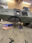
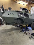
Take a look at the right rear wheel well of my V during maintenance and you'll see what I mean.
Also, the kit has the rear shocks attached to the axle on the kit, on the real V they are mounted to the top of the spring pack.

The V100 axles are the same as the M35, with slight interior differences not visible outside. The V wheels have six lug nuts. The V150 used the 5-ton axles, and has ten lug nuts. The differentials on the kit axles look a bit big, but its up to you if you want to fix that, since they will mostly be invisible. ;)

The hull is red in some of the pictures because it was in primer during most of the work.

Cheers

20240124_134459.jpg p18.JPG p22.JPG p23.JPG p19.JPG p24.JPG 20240124_142157.jpg DSCF8262.jpg p Int back.JPG
 
Last edited:

M813rc

Well-known member
Steel Soldiers Supporter
4,236
3,321
113
Location
Near Austin, Texas
Another note is the weld lines on the hull.
The kit is accurately moulded with a slight ridge where the sides meet the roof - that should be there, the roof plate overlaps the hull side very slightly.
There is another visible weld line at the rear side of the hull, which is not moulded on the kit.
The fold midway up hull side should be smooth all the way to the very front. The kit has a horizontal weld line above the front wheels that should not be there. There is a small vertical weld line where the upper hull slants in at the front to meet the window piece.

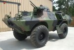
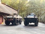
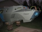
This picture of my V shows the visible weld lines. And also how unusually round the wheels look, minimal flat spot at the bottom.
These points should also be visible in pictures in the restoration thread, but if you need clearer pictures, or details not on there, just ask.

Cheers

Edit - it helps if I actually attach the picture! Now done.

ss24.jpg
 
Last edited:

wgtactical

Well-known member
674
316
63
Location
Carrollton, Georgia
Hey, no worries SW! Your first choice (sniff sniff...no, no I'm perfectly fine..) may have better under-hull pictures, he has dealt with more Vs than I can even dream of playing with. ;)

I took a look at the Hobby Boss lower hull (I bought the kit when it first came out and never got around to building it) and it is pretty far off from the V100!
The top hull section and the details are all very good, but that lower hull piece is for a V150

The openings under the V100 should be just big enough to go around the axles, and where the driveshafts go up into the hull.
The rounded outer opening for the wheel wells are accurate, but the wheel wells themselves should be done in flat sections rather than rounded. The very early Vs had squared outer openings but it was found that hull cracks propagated from the corners, so they were rounded and that solved the problem.

The rear shocks sit in cutouts at the rear of the wheel well, the top of which is accurate on the kit, but not that big square open area (circled in the picture). The shock cutout is on the inside of the wheel well (inside the vehicle) but is square rather than round as moulded in the kit. That axle slot is also way too big!
Take a look at the right rear wheel well of my V during maintenance and you'll see what I mean.
Also, the kit has the rear shocks attached to the axle on the kit, on the real V they are mounted to the top of the spring pack.

The V100 axles are the same as the M35, with slight interior differences not visible outside. The V wheels have six lugnuts. The V150 used the 5-ton axles, and has ten lugnuts.

The hull is red in some of the pictures because it was in primer during most f the work.

Cheers

View attachment 915289 View attachment 915283 View attachment 915284 View attachment 915285 View attachment 915291 View attachment 915290
M35 vs V100, with regards to the steering axle the spring locating pins are in a different location as well as a different steering arm with larger mounting bolts. The M35 housings can be changed to serve as V100 axles. Of course the attached picture shows a few more upgrades than that.
 

Attachments

M813rc

Well-known member
Steel Soldiers Supporter
4,236
3,321
113
Location
Near Austin, Texas
M35 vs V100, with regards to the steering axle the spring locating pins are in a different location as well as a different steering arm with larger mounting bolts. The M35 housings can be changed to serve as V100 axles. Of course the attached picture shows a few more upgrades than that.
Thanks, Gerald!
In my dreams my V has disk brakes, it would stop so much better!

Rooper, the disk brakes were not stock. :sneaky:

And I added a couple more pictures to post #7

Cheers
 
Last edited:

Buck Wampum

Active member
64
132
33
Location
SE PA
Hello!

I'm looking for the best possible photos of the lower part of the V-100 Commando hull, preferably around the front and rear axles.
I'm a modeller and I'd like to build the most faithful replica of the V-100 in 1/35th scale. I have the Hobby Boss XM706E2 kit but unfortunately the lower part of the hull is completely wrong and doesn't match the real machine.
I already have a few photos of the lower part, but unfortunately I'm still not able to faithfully capture the quite complex V-100 "chassis."
Thank you very much for any help.
PS: If it doesn't belong in this forum, please forgive me.

George K.

This is a video done of my V – 100 by John at East Coast Armory. He did a 1:6 scale V-100 vehicle. If you go to his Facebook page, he has about 400 photographs there that he took of my vehicle. He also has done the same thing for an E2 (open-top Air Force version of the V – 100).

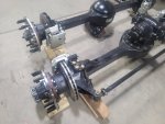
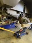
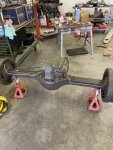
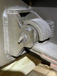
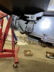
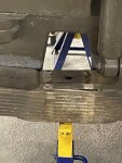
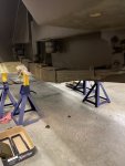
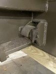
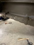
below are some photographs I took, when doing two rear axle swaps from V100’s. These are the ones I have handy on my phone. I also did a front axle R/R, but I don’t think I took many pictures of that.

IMG_4280.jpegIMG_4279.jpegIMG_2468.jpegIMG_2467.jpegIMG_2360.jpegIMG_2358.jpegIMG_2349.jpegIMG_2257.jpegIMG_2255.jpegIMG_2160.jpeg
 

Rooper90

New member
6
11
3
Location
Liberec Czech Republic
Hello everyone!

Thank you all very much for the valuable advice and especially the photos that will help me incredibly much in 3D modeling of the correct bottom of the hull.

I would also like to ask a few more questions if I may ask you as an expert
Specifically, what is the thickness of the hull side material, it is not possible to estimate from the photos, I would like to know what thickness of plastic plates I will use when scratchbuilding hull after conversion from real size to 1/35 scale.

And then I'd like to ask if one of the owners would be willing to measure some of the dimensions of the inner plates for me. Thanks to the "V" angle of the bottom and top of the hull, I can't capture the dimensions of all the inner plates of the mudguards. It's such a lousy job to run around a V-100 with a tape measure in your hand and write the individual dimensions on a piece of paper :D


And is there a digital version of the Technical Manual?
I haven't found it anywhere yet
Thank you all for your help

Best regards from the Czech Republic
George
 

Buck Wampum

Active member
64
132
33
Location
SE PA
Hello everyone!

Thank you all very much for the valuable advice and especially the photos that will help me incredibly much in 3D modeling of the correct bottom of the hull.

I would also like to ask a few more questions if I may ask you as an expert
Specifically, what is the thickness of the hull side material, it is not possible to estimate from the photos, I would like to know what thickness of plastic plates I will use when scratchbuilding hull after conversion from real size to 1/35 scale.

And then I'd like to ask if one of the owners would be willing to measure some of the dimensions of the inner plates for me. Thanks to the "V" angle of the bottom and top of the hull, I can't capture the dimensions of all the inner plates of the mudguards. It's such a lousy job to run around a V-100 with a tape measure in your hand and write the individual dimensions on a piece of paper :D


And is there a digital version of the Technical Manual?
I haven't found it anywhere yet
Thank you all for your help

Best regards from the Czech Republic
George
Hi George, the side of the hull is .250 inch. Floor of the hull is .375 inch

Somewhere in the V-100 forum here on Steelsoldiers, there is a digitized version of the Cadillac Gage parts manual. It was in a thread somewhere, you’ll have to do a search for it. The factory part number for the parts manual is 101927. Try a search on here for that number.

You can order paper copies of the technical manual from Portrayal Press (portrayalpress.com), the number is TM 9-2320-245-24. It’s $59 USD.

I’m kind of busy at the moment and can’t do the measurements, so if nobody else can do that, ping us again in a few weeks, and we have time to go out to the garage with a piece of paper and a tape measure.

Cheers,
Scott

IMG_4850.jpeg
 

Paweł

Active member
65
208
33
Location
Poland
Hello! I love this thread - I've been wanting to build a model of the Commando for some time now, but I was afraid of the chassis, and I love to have my models accurate from the underside too! The photos you show here are very helpful but I still hope for more. Thanks in advance and have a nice day
Paweł
 

Paweł

Active member
65
208
33
Location
Poland
Hello again!
I've just found this neat line drawing of the V-100 interior:
1707081741357.png

I'm bringin' this up, because after analyzing some photos I found looking at the interior gives you some good clues about how the underside must look like.

I would like to ask owners of actual M706s and people having experience on 'em for comments on the above drawing - do you find it OK, or do you see any faults or inaccuracies with it?

How about features like the shaft tunnel not being parallel to the sides of the vehicle - is that the way it really is built?

I just started cutting up the chassis of the Hobby Boss model, I'll try to make it better. I also see I badly need some scale deuce axles, the kit ones are oversize even for 5 ton axles.

Thanks in advance and have a nice day

Paweł
 

Attachments

Last edited:

Buck Wampum

Active member
64
132
33
Location
SE PA
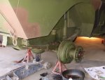
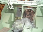
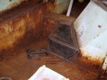
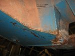
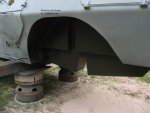
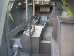
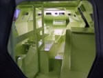
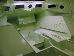
From the Green Room (the archives of the late Jim Green's estate), here are some hull photos of Jim's V-100 during restoration. Note that the hull in the rear axle area was modified to accept an air locker axle. You can see in the first photo of the engine compartment (before sandblasting) that Jim added a pocket to the hull accommodate the air locker cylinder on the Norwegian military rear axle. The second picture (taken from underneath the vehicle) shows the hull in original form, before it was modified. Hope this helps the modelers out there. No reuse of pictures without permission.


air locker hull mod (2).JPGhull markup before modification.jpgOct 2013 (30).JPGOct 2013 (33).JPGsandblasted (1).JPGSeafoam green (1).JPGSeafoam green (2).JPGunmodified hull 1.JPGunmodified hull 2.JPG
 

Buck Wampum

Active member
64
132
33
Location
SE PA
Hello again!
I've just found this neat line drawing of the V-100 interior:
View attachment 916041

I'm bringin' this up, because after analyzing some photos I found looking at the interior gives you some good clues about how the underside must look like.

I would like to ask owners of actual M706s and people having experience on 'em for comments on the above drawing - do you find it OK, or do you see any faults or inaccuracies with it?

How about features like the shaft tunnel not being parallel to the sides of the vehicle - is that the way it really is built?

I just started cutting up the chassis of the Hobby Boss model, I'll try to make it better. I also see I badly need some scale deuce axles, the kit ones are oversize even for 5 ton axles.

Thanks in advance and have a nice day

Paweł
Hi Pawel,
I added a post to this thread showing some hull shots. Yes the tunnel is at an angle to the hull. Please note that the tunnel is a sheet metal construction to shield the driveshaft to the front axle, and is not visible from the exterior underside of the vehicle. From underneath on the exterior, the floor of the hull is flat and smooth like a table top. Hope this helps.
Scott
 
Top
AdBlock Detected

We get it, advertisements are annoying!

Sure, ad-blocking software does a great job at blocking ads, but it also blocks useful features of our website like our supporting vendors. Their ads help keep Steel Soldiers going. Please consider disabling your ad blockers for the site. Thanks!

I've Disabled AdBlock
No Thanks