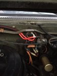
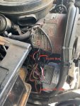
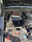
I recently picked up a M1010 truck and had some questions regarding the wiring for the lights. It seems like some things have been modified on the truck, so I am trying to understand what's been done. It almost seems that all the 12V wiring has been eliminated and everything is set up to be at 24V... is that something people do instead of 12V conversion? The lower alternator does not seem to be working at all right now(like 0.5V when running at the positive terminal with the pos wire disconnected), but the positive wire for it runs through a to a terminal on the firewall (im guessing the volt-meter) and directly to the 24V bus. The top alternator has a switch wired to it so you can turn it on/off, and also just goes to the 24V bus. So there doesnt seem to be a 12V charging system like Ive read with the DUVAC.
There also does not seem to be a 12V bus at all, the only wire on the positive terminal of the front battery (the "12V" one) is the one going to the negative on the back battery. I would expect there to be a wire here that runs to some sort of 12V bus like I've read online, is that correct?
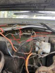
This all brings me to my recent discoveries where I finally figured out how to get the lights on (for some reason the horn was wired to the service lights on switch, so I had to disconnect that before I could see if the lights worked) and I flicked the high beams on and they turned on momentarily then the headlights and one of the front parking lights went out, seems like the bulbs got burnt out or something...? So my question is are those lights supposed to be 12V or 24V? By turning on my high beams did they get burnt up from getting 24V when its supposed to be 12? but then why would they be working before without high beams on... and why is one of the parking lights still working?
Hope that Is clear enough, Im just trying to get a grasp for how this is supposed to be set up so I can begin to understand how it is modified, any insight you have here would be helpful. Thanks!
There also does not seem to be a 12V bus at all, the only wire on the positive terminal of the front battery (the "12V" one) is the one going to the negative on the back battery. I would expect there to be a wire here that runs to some sort of 12V bus like I've read online, is that correct?
This all brings me to my recent discoveries where I finally figured out how to get the lights on (for some reason the horn was wired to the service lights on switch, so I had to disconnect that before I could see if the lights worked) and I flicked the high beams on and they turned on momentarily then the headlights and one of the front parking lights went out, seems like the bulbs got burnt out or something...? So my question is are those lights supposed to be 12V or 24V? By turning on my high beams did they get burnt up from getting 24V when its supposed to be 12? but then why would they be working before without high beams on... and why is one of the parking lights still working?
Hope that Is clear enough, Im just trying to get a grasp for how this is supposed to be set up so I can begin to understand how it is modified, any insight you have here would be helpful. Thanks!