• Steel Soldiers now has a few new forums, read more about it at: New Munitions Forums!

  • Microsoft MSN, Live, Hotmail, Outlook email users may not be receiving emails. We are working to resolve this issue. Please add support@steelsoldiers.com to your trusted contacts.

M1010 for my daughter the field biologist

Another Ahab

Well-known member
18,007
4,579
113
Location
Alexandria, VA
So it seems I have current flowing from the + side of the back battery into the 24V distribution block, back out through the 12V distribution block, and back into the back battery...

I have to work on my honeydo list for a while. When I can get back to the truck, I'll start pulling fuses and see if I can interrupt this current flow. I'll also start digging through the archives to see if this is a known issue.
I don't know Electricity, I confess, but i do WANT to learn, so excuse if this is stupid (wouldn't be the first time!), BUT:

- So you're thinking it's some kind of parasitic load or something, because this "shouldn't" be happening; is that it?
 

jpg

Member
611
15
18
Location
Boston, MA
I don't know Electricity, I confess, but i do WANT to learn, so excuse if this is stupid (wouldn't be the first time!), BUT:

- So you're thinking it's some kind of parasitic load or something, because this "shouldn't" be happening; is that it?
Sort of. My understanding of "parasitic load" is that it's designed into the device and intentional. Like if you turn your TV off, it isn't completely off. Part of it is powered up and "listening" for your remote to tell it to turn back on.

I have the electrical equivalent of a plumbing leak.

When you turn off a car, you want nothing draining the battery. This means you want 0 amps in a truck like ours. More modern vehicles have alarm systems, and they listen for you to push the button to unlock, so there is some parasitic drain designed into these. The CUCV has no such technology. As I understand it, when it's all turned off, there should be no current moving anywhere.

So the fact that I have current moving when it's all turned off means I have a problem somewhere. The usual M1010 culprit is a relay in the back, but that's supposed to stop drawing current when the Service switch is off.

The fact that the current seems to move between the 12V and 24V distribution blocks leaves me really puzzled...

The military added lots of diodes, suppressors, etc. to the CUCV to reduce noise on their radios. I suspect one of them is causing my leak... A leaking horn suppressor melted my headlight fuse the other day...
 
Last edited:

jpg

Member
611
15
18
Location
Boston, MA
jpg, your whole explanation here is completely understandable (which isn't always the case with electrical explanations):

- You could be a professor of Electrology!
I just hope it's correct. We have experts here on SS. They provide reliable information. I'm just a newbie.

Your local technical High School likely offers adult night classes that would teach you about this stuff, if you really want to learn it. They taught me to weld.
 

Another Ahab

Well-known member
18,007
4,579
113
Location
Alexandria, VA
I just hope it's correct. We have experts here on SS. They provide reliable information. I'm just a newbie.

Your local technical High School likely offers adult night classes that would teach you about this stuff, if you really want to learn it. They taught me to weld.
You are right, absolutely right. In fact, I picked up my welding at the local Community College (Northern Virginia Community College, NOVA).

It's just like, "WAAAAAAN, I don't wanna go to school!"


baby.gif

Say, we're not drifting here or anything, are we!?
 

tim292stro

Well-known member
2,118
41
48
Location
S.F. Bay Area/California
So here's what I would recommend doing first, pull the fuses for your 24v devices and then measure the current again.

One of the things you have to be careful of is backfeeding your 24v devices.

The second thing I'd check is the alternator wires for any current when the ignition is off - if your power wires are showing current, the diodes in the rectifier may be ready to go...

For the inverter and winch did you run a dedicated ground/return wire?
 
Last edited:

jpg

Member
611
15
18
Location
Boston, MA
I haven't installed the inverter or winch yet. I'm trying to get the basic truck running right before I make it more complicated. When I do install them, *should* I run a dedicated ground return wire? My instinct says yes, but I've read that it's better to use the frame. That seems like a lot of amps to turn loose on the frame...

I only measured the wires that connect directly to the battery. I have the Plan B mod, and the 12V alternator feed to the battery carried no current. The 24V alternator doesn't connect directly to the battery, so I haven't measured it yet. I will.

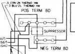
Since a failed horn suppressor melted my headlight switch recently, I have an eye out for failed suppressors. The ones depicted here could be leaking current to ground. Something else would also have to be failing for that current to then get into the +12V distribution block, but this might be part of the problem. Is there any reason to retain these suppressors? If so, I'm inclined to replace them with new ones.

supp.JPG

I was planning to tear these distribution blocks apart and clean/lube them. I was also planning to do the GP Resistor bypass while I was in there. Before I do, I'll learn what I can about where this current is going. I'll measure the wires leaving the +24V distribution block. I presume one of them is the 24V alternator. I'll also pull fuses and see what I can learn that way.
 

jpg

Member
611
15
18
Location
Boston, MA
Wayward amps

OK. I took lots of measurements, the sum total of which leave me confused. I'll start with the measurement that seems most significant. In the picture below, the heater control cable passes through the firewall into the engine compartment. 3 wires are together in a flat ribbon that passes behind the fuel filter. At the point where it plugs into the firewall near the arrow labeled 4, when I put the Fluke around the 3-wire ribbon it reads 2.7 amps. This is with everything turned off.

heatercable.JPG

The connector near 4 is only half-way seated and it looks corroded. I would have to remove the rear battery tray to unplug the connector. The 3 wires press pretty hard against the tray, so its possible insulation rubbed away and I have a short. When I put the fluke around the suppressor wire, I get 0.1 amps there.

I'd need to remove the rear battery tray to get a good look at the wires where they rub the battery tray, and to clean up and properly seat this connector. That of course means removing the battery and being unable to measure current. Tomorrow, I'll wrap them in tape as a temporary measure to be sure they're not shorted.

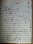
Here are the currents I measured, with the engine and the Service Lights off.
photo2.jpg

Tomorrow I'll start pulling fuses and see what happens. The heater works, so the ugly connector and rubbing wires might not be the culprits.

If our CUCV wizards have any suggestions as to where I should look next, I'm open to guidance. With the Fluke 375, I think I have the tools necessary to debug and fix this. But I don't have the necessary expertise.
 
Last edited:

jpg

Member
611
15
18
Location
Boston, MA
Tonight, the Fluke 375 showed 0.5A on the wire leading from the batteries to the 12V Distribution Block, and 0A on the wire leading to the 24V Distribution Block. I removed everything from the fuse block, all fuses, flashers, and the tap feeding my tinytach. It made no difference. So my problem lies upstream of the fuse block.

I need to go back to the wiring diagrams and look at the 12V circuitry on the engine side of the firewall. I poked around some with the fluke, and several wires running from the 12V distibution block had .3 or .4 amps.

Interestingly, the fuel lines to the passenger compartment fuel-fired heater carry 0.2 amps. Not the wire, the metal fuel lines. I measured a few inches from the pump. The wire feeding that pump had 0 amps.

I'm off to read wiring diagrams.

On a separate note, a PO did the GP Resistor bypass. From the 12V Distibution block to the GP relay, he used a much heavier wire than in the sticky, and no fusible link. What is the proper circuit protection to have there? The sticky mentions re-using a wire that I do not have.

I crawled under the dash looking, and I can find no courtesy light. If someone has a picture, I'd be very curious to know what it looks like.
 
Last edited:

tim292stro

Well-known member
2,118
41
48
Location
S.F. Bay Area/California
I haven't installed the inverter or winch yet. I'm trying to get the basic truck running right before I make it more complicated. When I do install them, *should* I run a dedicated ground return wire? My instinct says yes, but I've read that it's better to use the frame. That seems like a lot of amps to turn loose on the frame...
Good man, make sure the foundation is solid before building the house...

Yes, you should put in a ground return wire for heavy continuous loads, steel has about 20% the conductivity of copper (or 5x the resistance), and the frame is an imperfect conductor already, rivets bonding components, bolts and other points of corrosion... When I did SPL drag racing setups before it was a sport in the early days of big car stereos (the mid '90's), we always ran dedicated ground return wires. You're looking for maximum reliability on these devices, so don't go the Auto Manufacturer route of "ten more feet of wire will cost us $80 on five thousand trucks, so let's save a half million dollars by using the frame as a return path..."

...Since a failed horn suppressor melted my headlight switch recently, I have an eye out for failed suppressors. The ones depicted here could be leaking current to ground. Something else would also have to be failing for that current to then get into the +12V distribution block, but this might be part of the problem. Is there any reason to retain these suppressors? If so, I'm inclined to replace them with new ones...
If you plan on running any radios (UHF/VHF, WiFi), things that need to "listen" with (not just entertainment listening), the suppressors will cut the noise generated by the brushes in a motor as they slide from one contact to the next, or the rapid open close of a horn vibrator. These devices have rapid current draws followed by load dumps (in the multiple kHz range) usually coupled with a collapsing magnetic field that amplifies it. VERY noisy for RF.

...measurements, the sum total of which leave me confused. I'll start with the measurement that seems most significant. In the picture below, the heater control cable passes through the firewall into the engine compartment. 3 wires are together in a flat ribbon that passes behind the fuel filter. At the point where it plugs into the firewall near the arrow labeled 4, when I put the Fluke around the 3-wire ribbon it reads 2.7 amps. This is with everything turned off.
View attachment 584077

The connector near 4 is only half-way seated and it looks corroded. I would have to remove the rear battery tray to unplug the connector. The 3 wires press pretty hard against the tray, so it's possible insulation rubbed away and I have a short. When I put the fluke around the suppressor wire, I get 0.1 amps there. I'd need to remove the rear battery tray to get a good look at the wires where they rub the battery tray, and to clean up and properly seat this connector. That of course means removing the battery and being unable to measure current. Tomorrow, I'll wrap them in tape as a temporary measure to be sure they're not shorted.

Here are the currents I measured, with the engine and the Service Lights off.
View attachment 584083

Tomorrow I'll start pulling fuses and see what happens. The heater works, so the ugly connector and rubbing wires might not be the culprits...
If these wires in that bundle are not part of the same circuit (i.e. multiple parallel wires to-from the same two devices), you are likely seeing an error. You will need to separate them to isolate each circuit. Also, read up in the manual about the effect of wire location in the clamp on measurement error. If it's in the very center of the clamp loop, it's more accurate than if it's touching the side of the clamp. Also keep in mind that since the clamp is a hall effect device, external magnetic interference from things like permanent magnet motors within a few inches can skew the numbers.

For a measurement of 0.1A I would be suspicious of the accuracy in general - for something like than you can use the mVolt measurement across the suppressor to see if there is a voltage drop (it would be higher closer to the supply if the device had a loss to ground), the meter is accurate to 0.1mV (0.0001V) so it should see any appreciable voltage drop across the suppressor.

...I was planning to tear these distribution blocks apart and clean/lube them. I was also planning to do the GP Resistor bypass while I was in there. Before I do, I'll learn what I can about where this current is going. I'll measure the wires leaving the +24V distribution block. I presume one of them is the 24V alternator. I'll also pull fuses and see what I can learn that way.
I think you will find that if you planned to clean/lube these up you will learn as much about the wiring as you would by waiting to study and clean/lube later. If you are keeping the 24V NATO plug, why not keep the glow plugs/starter 24V?
 
Last edited:

jpg

Member
611
15
18
Location
Boston, MA
Yes, you should put in a ground return wire for heavy continuous loads
Will do. That was my instinct. I read some articles that said the frame was a better ground than a dedicated wire. I'm reluctant to send 300A of 24VDC into a frame. I want to control exactly where that goes.

If you plan on running any radios (UHF/VHF, WiFi), things that need to "listen" with (not just entertainment listening), the suppressors will cut the noise generated by the brushes in a motor as they slide from one contact to the next, or the rapid open close of a horn vibrator. These devices have rapid current draws followed by load dumps (in the multiple kHz range) usually coupled with a collapsing magnetic field that amplifies it. VERY noisy for RF.
I guess I'll need to replace the horn suppressor then, and any others that have failed. The PO also removed a bunch of suppressors, like the one for the windshield wipers, and I think he removed 1 of the 3 between the 24DC distribution blocks. Once I get the system working properly, I can add known-good suppressors back in.

If these wires in that bundle are not part of the same circuit (i.e. multiple parallel wires to-from the same two devices), you are likely seeing an error. You will need to separate them to isolate each circuit. Also, read up in the manual about the effect of wire location in the clamp on measurement error. If it's in the very center of the clamp loop, it's more accurate than if it's touching the side of the clamp. Also keep in mind that since the clamp is a hall effect device, external magnetic interference from things like permanent magnet motors within a few inches can skew the numbers.
I did read the manual carefully, such as it is. It's quite thin. It only mentions centering regarding the flex sensor. I did notice that proximity to other things can impact the reading substantially. I get a reading of 0.2A if I set the meter down on the metal above the headlight. I bet the heater motor is just on the other side of the firewall from where I got the 2.7A reading. I guess I should make a habit of taking a reading with the wire outside the clam, to see if something will be throwing my reading off... Is there a good place to learn how to properly use these meters? The manual is far too thin...

For a measurement of 0.1A I would be suspicious of the accuracy in general - for something like than you can use the mVolt measurement across the suppressor to see if there is a voltage drop (it would be higher closer to the supply if the device had a loss to ground), the meter is accurate to 0.1mV (0.0001V) so it should see any appreciable voltage drop across the suppressor.
It would be great if the current I'm detecting turned out to be a measurement error. I'm finding it very confusing. It varies from one day to the next. I was assuming that meant an intermittent problem, probably involving corrosion somewhere. Is there a reliable way to cross-check what the meter is telling me? I'm seeing current in the main battery cables. I don't see how measuring voltage would help me here. The Voltmeter does tell me what I expect to see, so the Fluke seems to be working OK... And I did zero the ammeter.

If you are keeping the 24V NATO plug, why not keep the glow plugs/starter 24V?
It turns out a PO did the GP Resistor bypass, presumably to avoid the cascading failure that can happen when one GP fails, and the resistor provides higher voltage to the others, causing more to fail, etc. Didn't you do a highly mathematical analysis of that failure?

I do plan to keep the 24V starter, and various M1010 systems use 24V, like the A/C and fuel-fired heater. My winch is also 24V.
 

tim292stro

Well-known member
2,118
41
48
Location
S.F. Bay Area/California
...I guess I'll need to replace the horn suppressor then, and any others that have failed. The PO also removed a bunch of suppressors, like the one for the windshield wipers, and I think he removed 1 of the 3 between the 24DC distribution blocks. Once I get the system working properly, I can add known-good suppressors back in...
I would recommend looking at non-GM specific potential solutions for RF suppression, once you broaded your view to things other than what the CUCV came with you will find many more options and sources. The most common method for reducing noise across (radiated energy) a fast "switching" device is to use a capacitor, to kill the RF noise which is carried away (conducted energy) the most common way to kill that is a choke (coil of wire around a ferrite). This article will echo what I just said, but you'll get a bit more depth than I have time for right now.

When taking care of RF radiating objects, a passthrough capacitor like the three GM put on the wiper motor and the one on the horn will reduce the effect of "sharp edges" in the current direction/flow - any time current changes rate or direction there is what equates to a "multi-car pile-up" of electrons, which sends out the "sound of the crash" as RF energy. If you can soften the change, it's like putting thick foam or pillows between each car, so the sound is much less (less radiated RF energy). The key is to get the capacitor as close as possible to the device generating the RF energy as any wire length between the capacitor and the device will act as an antenna (unintentional radiator). Quieting RF noise for FCC compliance was one of the things I did at my last job, it's both an art and a science (admittedly more science than art, the art comes into not affecting the performance of the thing we're quieting down, or its appearance).

If you are planning on putting on intentional radiators (antennas) for work related transceivers/receivers, I'd recommend doing some research on RF-bonding of vehicles. A diesel is less noisy than a spark ignited vehicle simply due to the lack of an ignition system, but some of the other issues (brushed motors, horns) are still there. If you put in modern LED fixtures or inverters, they often include high frequency switching power supplies which can radiate noise as well. The body can also act as many pieces of tuned RF metal which resonate at different frequencies - even your exhaust system can act like an antenna...

...It would be great if the current I'm detecting turned out to be a measurement error. I'm finding it very confusing. It varies from one day to the next. I was assuming that meant an intermittent problem, probably involving corrosion somewhere. Is there a reliable way to cross-check what the meter is telling me? I'm seeing current in the main battery cables. I don't see how measuring voltage would help me here. The Voltmeter does tell me what I expect to see, so the Fluke seems to be working OK... And I did zero the ammeter...
For very low current (<5amps) temporarily putting a current shunt in the circuit is safe - I mentioned via PM that I prefer to not use shunts in high current applications as they generate a good deal of heat as they approach their rating. If you don't want to go buy a retail shunt, just any resistor will do as long as it's power rating is sufficient: measure it's resistance outside of the circuit, then install it in series with the circuit being measured, then measure the voltage across it. Ohms law is what you use for figuring out how much current is flowing across the resistor:

Code:
 E
---
I*R
Where E = Volts, I = Amps, R = Ohms. Divide the measured volts by the measured ohms and you'll get the current flowing across the resistor. If you have a choice in resistors, something that will amplify the measurement like a resistance of 10 Ohms or less (and multiples of ten makes the math easier). For instance a 10Ohm 50Watt resistor that shows 10milivolts across it works out to:

Code:
0.010Volts
---------- = 0.001 Amps or 1 milliamp
  10Ohms
This is safe because it's only using 0.01V * 0.001A = 0.00001 Watts or 10 microwatts (volts x Amps = Watts [power]). You can work out that this same 10Ohm 50Watt resistor will be safe for measurement up to 2.5Amps. Being in the millivolt range your Fluke 375 has an accuracy of +/-250microvolts or 0.00025V, so for measuring 1 milliamp your error would be +/-2.5% (very tight). Keep in mind most indicator type LEDs draw about 10-20 milliamps, so we're not talking a lot of power.

If you need to measure more amps, use a smaller resistor (1Ohm [100Watt is good for 10Amps], 100milliohm, etc...) with a higher power rating.

...It turns out a PO did the GP Resistor bypass, presumably to avoid the cascading failure that can happen when one GP fails, and the resistor provides higher voltage to the others, causing more to fail, etc. Didn't you do a highly mathematical analysis of that failure?...
I did - and if you don't use self regulating glow plugs the resistor system is fine. If you do use self regulating plugs (which have a variable resistance), I prefer to still keep the 24V supply but use something like 24V-to-12V DC/DC regulators for each plug (yes, 8x 25A regulators - takes about as much space as the two resistors, a little more). This way a standard 24V NATO jump plug can still be used to jump the truck (as glow plugs are needed to preheat the engine most of the time), but the energy efficiency of the glow system jumps immensely (from 50% to 90%+) and you can't have cascade failures since the voltage is limited.

...I do plan to keep the 24V starter, and various M1010 systems use 24V, like the A/C and fuel-fired heater. My winch is also 24V.
Try to keep as much of the original split system the same, it helps with troubleshooting later even if you swap say a ballast resistor pack for glow plugs with voltage regulators the function and design of the system stays intact for easy help later. Big devices with big power draw do better at higher voltages, that also means your cable size for the specific power demand will be about half the size (roughly one AWG step higher).
 
Last edited:

jpg

Member
611
15
18
Location
Boston, MA
Tire Pressure?

GM Service Manual gives the following max loads for differnt tire pressures for E rated radials on C-K trucks.
36PSI 1742 lbs
44PSI 1984 lbs
51PSI 2205 lbs
58PSI 2425 lbs
65PSI 2623 lbs
73PSI 2844 lbs
80PSI 3042 lbs


The data plate on my truck says the max load is 3685 on the front and 5765 on the back. That's 1842.5 on each of the front tires, and 2882.5 on each of the back. The curb weight is 3485 rear and 3885 back. That's 1742.5 on each front tire and 1942.5 on each rear tire.


The tires, E-rated Goodyear Wranglers, say max pressure is 80 PSI.


So I guess I can see where the TM gets 45PSI on the front and 65 empty/80 loaded on the back.


This info tells me how far I can safely air down in off-road situations, and my not-to-exceed pressure. It does not tell me what pressures to run for daily driving and/or highway use. Is there a source for guidance on that?
 

jpg

Member
611
15
18
Location
Boston, MA
As an experiment, I dropped the air pressure in my front tires from 58 to 50PSI. Yuck! The truck seems to lean all over the place. But I can't get it to death wobble any more...
 

jpg

Member
611
15
18
Location
Boston, MA
Loose belts

My belts were loose. To measure belt tension, I got a Dayco Krikit
[video=youtube;z11wfc-0-hY]https://www.youtube.com/watch?t=168&v=z11wfc-0-hY[/video]
Amazon sells it as "Gates 91107 Belt Tension Tester"

To help with tensioning belts, I got a Lisle 12400, and used it with a 24" breaker bar.

lisle12400.jpg

Table E-2 in TM9-2320-289-20 lists the tension for old belts as 67 lbs. New belts get run for 15 minutes at higher tensions, 169 lbs for A/C compressor, and 146 for others. After 15 minutes, they get re-tensioned as old belts.

The alternators have one pivot bolt and another that rides in a slot. You loosen the bolt in the slot, move the alternator until the tension is right, and tighten the bolt again. You have to use a fair amount of force. I could clearly see my breaker bar flex as I did this. You have to be very careful where you attach the tool you use to adjust tension. It's very easy to break fragile things when applying that much force.

The A/C compressor has 2 bolts that move in slots. The Power Steering pump sits in a bracket that has 3, one of which is hidden behind and below. Look at the TM pictures and it will become clear.

I found this thread helpful:
http://www.steelsoldiers.com/showthread.php?65061-M1009-Power-Steering-Belt-Replacement

My lower alternator belt was loose enough that it rubbed a hole in my lower radiator hose. Bummer. I'll be checking my belt tension more frequently now. Learning lessons the hard way once again.
 

Another Ahab

Well-known member
18,007
4,579
113
Location
Alexandria, VA
My belts were loose.

My lower alternator belt was loose enough that it rubbed a hole in my lower radiator hose. Bummer. I'll be checking my belt tension more frequently now. Learning lessons the hard way once again.
That's the funny thing about learning though:

- The easy lessons you might tend to forget now and then

But the HARD and merciless lessons you just never forget. And that has it's good sides. And its bad sides, you know?

(PS "Calibrated Thumb Method"; that's pretty funny!)
 
Last edited:
Top
AdBlock Detected

We get it, advertisements are annoying!

Sure, ad-blocking software does a great job at blocking ads, but it also blocks useful features of our website like our supporting vendors. Their ads help keep Steel Soldiers going. Please consider disabling your ad blockers for the site. Thanks!

I've Disabled AdBlock
No Thanks