• Steel Soldiers now has a few new forums, read more about it at: New Munitions Forums!

  • Microsoft MSN, Live, Hotmail, Outlook email users may not be receiving emails. We are working to resolve this issue. Please add support@steelsoldiers.com to your trusted contacts.


M1031 PTO Governor Control - Factory Technical Manual

Keith_J

Well-known member
3,657
1,313
113
Location
Schertz TX
I have found the Goldilocks adjustment for this governor system. Make sure all switches, sensors and crimp terminals are correct, found one loose only by the heat it was generating.

Gain set to 70%, this varies based on actuator and engine. Integral (I) at 40%. Droop zero with S1 off, S2 on.

The actuator has a 35° throw. Pictures in the factory instructions don't work with the 6.2 IP too well as the initial throttle movement is collapse of the low idle spring. I set the actuator arm to about 45° in the off position. This makes the pushrod movement nearly linear to the actuator rotational. If set up per factory pictures, initial actuator movement results in little pushrod movement.

Results? I have three 3500 W water heater elements set up in delta, these are 240 volt elements so figure 3200 W at the measured 216 volts. Solid 60.4 Hz,+-0.20 Hz. Heats 5 gallons of water fast. But wait, there is more! Drained the air tank and flipped the breakers for the compressor. Still running 60 Hz solid with this additional 2 kW!

About 6 years ago, in a store parking lot, a stranger approached me and said he had worked at Able Body Corporation during the contract for these vehicles. He mentioned they had many issues with the integration of the system..

The engine should be around 1400 RPM to spin the generator at 1800 RPM to get 60 Hz. This creates a 480 Hz signal in the magnetic pickup circuit, around 5 volts AC. The rotor of the generator is a 4 pole, the MPU gets its signal off the PTO output spur gear so that is why the frequency is much higher in the MPU.
I will test the generator tomorrow with my 50 amp plasma torch. Specs say 30 amp load at 240 volts but it has a 12 gauge cord. The generator is good for 41.6 amps at 208 volts.
 

Attachments

Last edited:

Keith_J

Well-known member
3,657
1,313
113
Location
Schertz TX
Just finished tests running my 50 amp plasma torch off 208 single phase with the air compressor running. This is an inverter type machine which means highly reactive power, diodes first rectify the AC, charging a large capacitor bank. This causes a leading power factor. When the compressor is running, it's power factor is lagging since it is inductive, nameplate is 0.8 power factor.

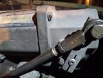
I set the plasma torch to maximum, digital readout indicated 51 amperes. Plasma typically runs 90 to 100 volts open circuit, a lot of power through the 12 AWG 2 conductor . The machine ran like on utility power, cutting 3/8" stainless about a clean as can be expected. Before, the arc would cut for 4 seconds, then extinguish for a second before restriking. And the engine speed would be all over the map.

This Lima MAC generator is well suited to both types of reactive loads with the output current induced rotor field. As output current increases, rotor current also increases which increases magnetic field in the rotor, offsetting voltage drop. No automatic voltage regulator can compare in reaction speed.

Now I have unlimited metal cutting up to 1/2" sever, 3/8" clean cuts. Easier to set up than oxyacetylene torch, I have 50 feet of 10 AWG extension cord and air hose. The inverter is only 12 pounds. Plus it cuts all metals, not just carbon steel.
 

Keith_J

Well-known member
3,657
1,313
113
Location
Schertz TX
I may need to back off the governor adjustment. The Lina MAC generator voltage regulation uses output current to induce rotor excitation current. This compounds the excitation since output current is AC, rotating twice as fast. This gives the generator great current capacity for starting electric motors and a definite voltage to speed curve. When the generator turns at 1500 RPM, voltage drops to 160 from a rated 208 at 1800 RPM.
At rated output of 12 kW, it needs an engine with 25 Hp output at 1800 RPM. As geared through the PTO, the engine spins around 1400 RPM, at this speed and full throttle, there is about 60 Hp available. The main circuit breakers are rated at 45 amperes, faults upstream could cause serious damage.

I now need to adjust the throttle linkage so in the case of internal problem, the resultant load drops the generator speed, dropping voltage to protect windings.

A useful addition would be output current meter. Or a torque cell. 75 foot pounds at 1800 RPM is 25 horsepower.
 
  • Like
Reactions: rtk
Top
AdBlock Detected

We get it, advertisements are annoying!

Sure, ad-blocking software does a great job at blocking ads, but it also blocks useful features of our website like our supporting vendors. Their ads help keep Steel Soldiers going. Please consider disabling your ad blockers for the site. Thanks!

I've Disabled AdBlock
No Thanks