• Steel Soldiers now has a few new forums, read more about it at: New Munitions Forums!

  • Microsoft MSN, Live, Hotmail, Outlook email users may not be receiving emails. We are working to resolve this issue. Please add support@steelsoldiers.com to your trusted contacts.


M1031 to RV tug..

Keith_J

Well-known member
3,657
1,313
113
Location
Schertz TX
Under 600 while towing?!
Not ever going to happen. I try to keep EGT under 600°F at 65 MPH unloaded but things like hills and headwind will cause rises to over 1000. Hence the need for water injection.

Adding mass of water is equivalent to high EGR rates in a modern diesel but without increase of manifold pressure which causes higher back work ratio (from increased work in compressing the charge when the piston rises)
 

Keith_J

Well-known member
3,657
1,313
113
Location
Schertz TX
Life has been in a holding pattern for a year with family illnesses but I've been acquiring parts..
I have the transfer case to 4l80 adapter (Advance Adapter), factory throttle position sensor and Dakota diesel tachometer interface.
Next is engine mount adapter plates and the 6x transmission.

The turbos arrive today, going to take time to fab manifolds for exhaust and modify a stock intake. Going to block off the intake, plumb 2 inch lines from compressors where existing CDR lines are and make a 3 inch spacer between the intake and air filter for compressor intake. Stock filter.
These turbos are good for 150 Hp each. Plus they will spool up at 1200 RPM. 10 psi boost at 1800 RPM. This will prevent smoke down low. Using analog computer to control the variable nozzles. Basically a simple voltage sum of TPS (0 to 5 volt) and RPM (0 to -5 volt). This sum will then encode a PWM module at 20 Hz to vary the vacuum on the VNT vane actuators.
 

Attachments

Keith_J

Well-known member
3,657
1,313
113
Location
Schertz TX
Back to work on the 1031..now a bit different. I was in a car accident and suffered nerve and tendon damage to my left arm, slow healing. But I have time to get some work done. And I have a Soldier B.

First item are head gaskets. Cooling system gets pressurized when cold so I have been running with the pressure lever on the cap lifted. Have new gaskets with ARP stud kit.

When the injection pump is out, it will get new seals on the throttle shaft plus the 1/4 turn on the leaf spring screw.

Next project is forced induction. Using a pair of modern variable vane units which flow about 20 pounds per minute..this mass flow will provide about 7 PSI of boost at 3600 RPM without any need for intercooling. Building exhaust manifolds out of pipe elbows, they will sit right next to the rocker covers. The stock intake manifold will be modified by drilling out the CDR ports to 2 inches and removing the middle web, then bolting a cover. Stock air cleaner will still fit like the ATS system, providing filtered air to the turbos.

The trickery is control of this system as variable vane turbos can spool instantly with the vanes closed. I found a stand alone controller specifically for these turbos, just have to import it.from the UK. The system fails safe in the low boost position.

My design of this system is to provide 7 to 10 PSI of boost from 1200 to 3600 RPM to keep exhaust smoke at a minimum with a good bit of additional torque throughout the range. The exhaust manifolds look to be easy to fabricate log style using 1-1/2 weld fittings in 304 Schedule 10 (0.109" wall thickness). 12 short radius elbows and 6 tees. Basically 200 dollars in pipe fittings, 500 dollars in turbochargers and another 500 in parts. About the same for a good single turbo but no lag and minimal choke. Plus good looking manifolds.
 
Last edited:

Keith_J

Well-known member
3,657
1,313
113
Location
Schertz TX
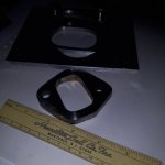
Gaskets that were on backorder arrived so I was able to make header flange pattern. Using a spare manifold for a jig instead of a head..lighter and more economical. Each runner will have an individual two bolt flange so I need 8. Three feet of 2.5 inch wide 3/8" stainless will do it with leftover for turbo flanges. Lots of plasma torch time..quote is out for laser cutting.

I am expecting some distortion, individual flanges will allow for cold setting to correct. Another reason for schedule 10 pipe. Stainless moves a lot as it has higher melting point and 50% greater thermal expansion. It also requires back purge or shielding, I am using Solar Flux B to protect the inside from chrome oxidation. All GTAW with autogenous root weld and 308L fill.
 

Keith_J

Well-known member
3,657
1,313
113
Location
Schertz TX
Gaskets are in..made a precise drilling template for the turbo exhaust flanges and one for the head flanges. Going to make them all myself..

My truck powers my plasma torch so I have a specific sequence of operations. The TIG welder can run off house 240 volt as stainless is thin. But cutting 3/8" stainless needs truck power.
 

Keith_J

Well-known member
3,657
1,313
113
Location
Schertz TX
This is how the fittings will be assembled to make turbo manifolds. The spaces will be short cuts of pipe, 5/8" or so. The ells coming out of the drawing will be ovalized on the cylinder head to match the individual flanges. This is inverted compared to the stock exhaust manifolds, the head ells turn up. Once the tees and ells are finished and aligned, the outlet tee to the turbo will be between cylinders 2 and 4 on the passenger side, 2 and 3 on driver's side. Remember, twin turbos. Lots of cutting but manifolds with smooth transitions and ideal volume to preserve exhaust velocity. Hot exhaust at peak velocity assures rapid boost. This is one drawback of the Banks and GM systems.
Weight of the manifolds will be about 8 pounds each, stock are 13. 20220316_121525.jpg
 

Keith_J

Well-known member
3,657
1,313
113
Location
Schertz TX
Got some pipe cut tonight..stainless is tough to cut with an old fashioned pipe cutter. But no kerf loss, minimal mess and square cuts are a benefit. Need 8 pieces, 0.75" long. That is a inch saved over cold sawing.

Tack welding in the morning. Then gentle squeeze of the port ends to match the heads.
 

Keith_J

Well-known member
3,657
1,313
113
Location
Schertz TX
8 welds done, only one needs rework..not too shabby for having a bum hand. 26 parts became 12 so cutting the parts count feels great.

Stock manifolds turn down, these will turn up. Since this is Schedule 10S pipe and fittings, it is much stiffer than any single piece flange. Which is why flanges will be welded last. And why individual flanges are a must. Along with bolting tubes, long bolts are more compliant and run cooler.
I still have to test fit where the turbo outlets will be placed. For that, the current exhaust manifolds need to be pulled. After that, heads will be pulled for inspection, gaskets and studs. Valve job while they are out.

20220319_213259.jpg
 

Keith_J

Well-known member
3,657
1,313
113
Location
Schertz TX
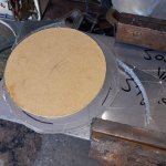
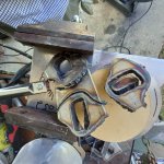
Have a plan..and a backup. I made plasma templates out of 1/4" MDF for cutting manifold flanges, thinking 3/8" stainless would cut fast on 50 amp plasma torch and the 7/16" torch offset would prevent charring. Well, extension cord voltage loss p!aged the plasma torch and patterns began to char. Before total loss, I remade templates from 1/4" aluminum plate. Then I made a 3 conductor #8 extension cord.

Hopefully more progress this week. Last week the red flag warning postponed any plasma torch work. Nothing caught fire..just one flange made with a lot of repair welding needed.

One down, 7 to go. Head side surface ground, the other side will be corner welded to the exhaust runner.

On the thermodynamic side, I found hard numbers from GM on volumetric efficiency..88% at 3600 RPM. Also, maximum EGT there is 1230 °F.

What this means for this engine with 10 PSI boost is a mass flow of 36 pounds of air per minute without intercooling.
20220406_204533.jpg
 
Last edited:

Keith_J

Well-known member
3,657
1,313
113
Location
Schertz TX
Back to thermodynamics, with mass flow of air at 26 pounds per minute and injection volume of 48 mm^3, the air/fuel ratio is 20:1. Boosted with mass flow of air at 36 pounds per minute, matching the a/f ratio means injection volume of 67mm^3.

The IP plungers are 0.290 inches in diameter, meaning a stroke of 1.126 mm delivers 48mm^3. The additional 19mm^3 would require a stroke 0.449 mm longer. This is a twin plunger pump so 0.2245 mm, that is 0.0088". Stock tune has a max plunger to plunger dimension of 1.977", that will increase to 1.994".

Anyone have a cam ring and micrometer handy? Trying to see if the stock pump will work. This is looking like 220 horsepower..
 

Keith_J

Well-known member
3,657
1,313
113
Location
Schertz TX
I did the rest of the plasma torch cutting today..some ugly, got three flanges in need of weld repair. Still have over 2 pounds of 309L in various diameters. Going to go fast now I have a pattern. The 1/2" carbide burr is still perfectly sharp, removes metal fast and doesn't heat the parts. Yeah, could have sprung on water jet cutting but I didn't want to measure, draw, test, measure, draw...

Now for the intake side, I cut the intake manifold block off plate from 1/4". Very nice, it cuts much easier than 3/8" 304L with plasma. This design is similar to the ATS top hat, using the stock filter. Compressor outputs will enter the stock manifold where the current CDR inputs. 2 inch diameter each plenum side. I'm still welding the exhaust manifolds, got 24 pieces down to 8. All the internals are cleaned and full penetration after using Solar B flux. Remaining welds will be back purged.

Received some nice quality cobalt HSS drill bits. Experimented with a tallow-steric acid emulsion coolant for drilling, amazing results. 3/16" pilot, then 3/8", 7/16" and 1/2". Only 4 outer flanges will get 1/2" holes.

Also got the metric banjo bolt sets for engine oil to turbos. Going with 1/4" OD CuNi tube, silver soldered to fittings. Will have to test the oil flow rate, the turbos need 0.30 GPM at 30 PSI.

It was a good day. I'm beat.
20220407_122239.jpg20220407_122239.jpg

20220407_122343.jpg
 

Keith_J

Well-known member
3,657
1,313
113
Location
Schertz TX
My welding skills with one and one-half hands plus OCD to achieve full penetration welds makes for ugly stuff. So these will not have beautiful welds. Also, dimensions are being held with zero root gap process, a tricky option on 0.109" wall. All low carbon 304 so it doesn't really matter. Strength over looks. That is why all welds are buffed smooth on the OD.

This is a complex system..intake plus exhaust and oil supply with return. I try to spread the work around, already acquired oil supply bits, some banjo fittings bored to 1/4" for brazed hard line as it reduces failure points. Turbos require 1.25 liters per minute at 30 PSI, no issue there. Now I have to make 1/2" ID lines to drain oil plus blow by leaking from turbine and compressor shaft seals. And route it to the crankcase, both sides. Again, I am the wrench spinner so design must include my service time. 2 hours additional design and Fab time to save a minute of service time is golden with sprinkles.

My exhaust manifolds show this, glow plug swap and injector service will be easy, no disassembly required. Even the air intake will be as easy as stock, pull the air cleaner, two spring clamps and 4 bolts removes the top hat.
Still on the fence if the oil supply lines need unions. I'm an open shop guy and an oil supply line being critical should have minimal fittings. Besdes, removing would be required for valve cover access and that is constrained by injector lines.

The trick for 0.109" wall thickness pipe with no root gap is by high amperage root gap, lay wire fill and cap. .109" stainless is normally done with 75 to 90 amps since stainless is a poor conductor. Using 110 amps pulsing without filler works, knowing when you get full penetration is art. Watching the weld pool will indicate when the weld is full penetration.

The gas tungsten arc has a powerful magnetic field created by the current, no need for Maxwells Equations for the why and what. The temperatures involved plus the stainless 304 means no arc deflection but remember, induction creates eddy currents in a magnetic field. Non molten metal reduces the eddy current effects in the weld pool. Once the swirling weld puddle is seen, back off the current and move forward. Definitely move forward once the puddle dips, the swirling puddle gives a prediction of incident puddle fall through.

Korean guy above has great video. He does filler rod addition to freeze the puddle and prevent drop out. I use no filler on root, then filler for cap and fill in the lay wire method like in the video.

Stainless steel at fluid temperature burns easily, the chromium and nickel are pyrophoric, forming a black slag called sugaring. I have used Solar Flux B on joints where I can clean from the inside. All other root welds are done using argon purge. Cap and fill are done with pipe full of water, this increases fill rate and makes heat not an issue. No burn through possible.
 
Last edited:

Keith_J

Well-known member
3,657
1,313
113
Location
Schertz TX
Grinding stainless is a pain. Especially 3/8" thick flanges..got half of them, that is 4, outside ground from the ugly plasma torch action. The inside grinding is a bit easier with 1/2" diameter carbide burr but makes a bunch of needle sharp mess.

Now to match drill the bolt holes. 1 down, 7 more to go. Using a bushing and spotting drill with a right side manifold. Bolt holes drilled tight for jigging on actual head. Once fully welded and aligned, bolt holes will be reamed to match actual manifold diameters (larger diameter on outer ports). This allows thermal expansion. Long bolts with bolting towers will increase bolt elasticity, preventing sealing problems. Plus these aid wrench access.

Making the pipe ends oval for port matching is easily done with a large bench vise. One down, 7 more.
 

Keith_J

Well-known member
3,657
1,313
113
Location
Schertz TX
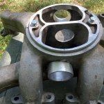
Needed to balance work and get things made on the intake. Basically lifting the stock air filter 2 inches with a collar. The collar has a 1/4" plate on the bottom, gasket sealed and 4 bolts. Two are the air filter hold down studs, two more added by welding bosses inside each plenum.

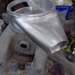
Filtered air travels down two 4" X 1" windows in this collar, into a funnel which transitions into 2" tube to each compressor inlet.
 

Attachments

Keith_J

Well-known member
3,657
1,313
113
Location
Schertz TX
Almost finished with the cold air side. Stock manifold modified for the compressor outlets. 1.80" ID spools fit into each bank for the O ring sealed tubes from compressors. 20220512_145837.jpg20220508_182346.jpg

Welds were difficult due to access and heat. Blew through 10 tungsten electrodes and still have half of the second tube.

The great thing about this project is when I get frustrated, there is always something other to do.
 
Last edited:

Keith_J

Well-known member
3,657
1,313
113
Location
Schertz TX
The problem weld area is the boost tube right between the high middle runners. After cooling down and putting a 1/4" ball end carbide into the collet, short work with the die grinder.

This tool has been used most in this project, mostly port matching the exhaust manifold flanges. Quality carbide is a must with this 34,000 RPM tool.

I also played around with torch configuration, looks like Pyrex cup gas lens stubby kit with button end cap will work from the inside. Good to know for the exhaust manifold flange welds as these will be inside welded all around, stitch welds top and bottom on the outside. Don't want to interfere with bolting.

I have a 17 series torch, had used the standard collet and nozzle setup for 10 years before going to gas lens. Standard collet and nozzle is over 2 inches long, gas lens is half that. Tungsten electrode comes in 6 inch length, a hollow back cap quill adds to overall length. Eventually, tungsten electrodes need regrinding especially when I dip into the weld pool. Short electrodes are needed for the short back cap, even shorter for button back. So I dug into my box for my worn out tungsten..these are old school and doped with thorium, a mildly radioactive element. So grinding must be done outside and masked. I've been doing this for 26 years, only in the past 10 have cerium doped electrodes been more available.
 
Last edited:
Top
AdBlock Detected

We get it, advertisements are annoying!

Sure, ad-blocking software does a great job at blocking ads, but it also blocks useful features of our website like our supporting vendors. Their ads help keep Steel Soldiers going. Please consider disabling your ad blockers for the site. Thanks!

I've Disabled AdBlock
No Thanks