• Steel Soldiers now has a few new forums, read more about it at: New Munitions Forums!

  • Microsoft MSN, Live, Hotmail, Outlook email users may not be receiving emails. We are working to resolve this issue. Please add support@steelsoldiers.com to your trusted contacts.

M1078 Hydraulic Controller Box and System Schematics

Lugnuts

Active member
Steel Soldiers Supporter
319
236
43
Location
Myakka City, FL
I don’t do sarcasm, I am a very literal person. I am removing all my mid structure and am replacing all the hydraulic control with a hand pump. I literally need to use it to lower the spare tire one last time then I am done with the valve…

Thank you for the clarification Ronmar. Can I contact you on a personal message as to what you would consider? Thank you for the video link
 

Lugnuts

Active member
Steel Soldiers Supporter
319
236
43
Location
Myakka City, FL
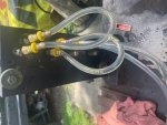
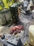
So here's what I got going. Thanks to Ronmar I have a working Hydraulic Control Box and Air Pump. So I set it up to test flows and what I speculated would happen when I flowed oil. The Controller worked great and gave me a platform to work from for when I get my other Box home I can figure out what is wrong with it. I'll post what I find out then.
I do have to say that even with no load on the plumbing that the pump will blow those vinyl lines off the Push Lok fitting in a heart beat but if you pump really very slowly that you can create oil flow and watch how the air bubbles travel and if it reverses when you switch the polarity and the whole function.
Thank you Ronmar and I will post my findings later when I test the other unit.Hydraulic Control Box.jpgHydraControlBox.jpg
 
Top
AdBlock Detected

We get it, advertisements are annoying!

Sure, ad-blocking software does a great job at blocking ads, but it also blocks useful features of our website like our supporting vendors. Their ads help keep Steel Soldiers going. Please consider disabling your ad blockers for the site. Thanks!

I've Disabled AdBlock
No Thanks