• Steel Soldiers now has a few new forums, read more about it at: New Munitions Forums!

  • Microsoft MSN, Live, Hotmail, Outlook email users may not be receiving emails. We are working to resolve this issue. Please add support@steelsoldiers.com to your trusted contacts.

M1078A1 voltage issues/no power

Wingnut13

Well-known member
Steel Soldiers Supporter
233
560
93
Location
Strafford, NH
Well yesterday was a nice day, went for a ride. Parked the truck last night. Worked on routing electrical wires for the Boss snow plow …. But hooked up NOTHING…. Had everything in place and was ready to make a beer run. I turned the power switch on and Voltage showed low, 22-24VDC, huh, I didn’t leave the lights on overnight or anything dumb as far as I can tell.

I tried to start the truck and the starter clunked a couple times, then everything went dark, just like when a capacitor dies…… slowly, not just everything shuts off instantly. Oh boy.

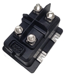
I found nothing out of sorts initially but then found 12vdc on the alternator 24v side, 0vdc on the 12v side. Huh. I then expertly smacked the side of the battery shutoff box, power came on! Ok, open the box and check out connections. I found some extremely corroded connections. Spent the better part of 2 hours cleaning and replacing wrong sized washers etc.

After all this I hooked the battery’s back up and verified voltage in and out of the battery disconnect box. Everything looked good there. However up at the LBCD I’m only showing 12v on the 24v side and 0v on the 12v side…..

Tomorrow I’ll fix up those connections. But I’m the meantime, the Alt still has 12v on the 24v side and 0v on the 12v side.

Anyone have any ideas?
 

Ronmar

Well-known member
3,322
6,696
113
Location
Port angeles wa
While you are doing connections, do the starter as well. Your main ground goes from the battery to the terminal on the front of the starter motor. From there you will find a ground strap that connects the battery ground to the drivers frame. That is your main chassis ground.

When you were measuring voltages in the battery box, what were you using as a ground reference for the meter? Everything that needs a ground on the truck(everything…) is using the chassis ground…
 

Wingnut13

Well-known member
Steel Soldiers Supporter
233
560
93
Location
Strafford, NH
I’m working through all the power connections, cleaning as I go. I’ve found something I’ve got a question about. On the tip connection of the LBCD there is a lighter gauge wire with fireproof sleeve on it. It seems to have a really floppy kink in it. See the picture. Anyone know what’s under there?39820A61-449C-425B-939F-3FF4BDFB40F7.jpeg
 

GeneralDisorder

Well-known member
Steel Soldiers Supporter
1,514
4,207
113
Location
Portland, OR
There's an Army PS magazine blurb about those early relays having bad connections and mine had a solder joint problem inside the potted control box.


There's a new enclosed unit that replaces the early ones:


Here's a good deal on a new surplus unit:


Wingnut13

Well-known member
Steel Soldiers Supporter
233
560
93
Location
Strafford, NH
So I pulled out the relay block, found the diode bridge thing had broken the rings off on both relays. So I put new diodes on. I tested both relays for operation and they cu-chunk on the bench pretty good. Once they are back in the truck and hooked up the cu-chunk noise is…. Less than impressive. So yeah there may be a bad solder joint under that conformal coating.

Did you find and fix your issue with the bad solder joint?

I did find that Army article and that’s why I pulled mine.
 

Wingnut13

Well-known member
Steel Soldiers Supporter
233
560
93
Location
Strafford, NH
Got it fixed. As per standard I’m the cause of most of my issues…. The first no start was due to bad connections in the disconnect area, and I also found issues with the relay diodes which I replaced. But in my haste to finish the fix I hooked up the main ground to the wrong terminal giving odd readings and no power to the cab. She’s all cleaned up and running now. Much thanks to those who helped with guidance!

the washers at the bottom there were UNDER the battery terminal leads at the disconnect switch!

the picture of the broken ring is from the relay diodes that goes up and over the top of each relay. The fix is shown with some rather large diodes I had in the shop.CD3407A3-32BD-46AF-83C0-B3B798A3621F.jpeg77AA8A16-2400-408E-85D7-24AC77FDE961.jpeg
 

GeneralDisorder

Well-known member
Steel Soldiers Supporter
1,514
4,207
113
Location
Portland, OR
I replaced mine with the new style but I did pull that box off and found the loose ring so I heated it with a small torch and after letting it cool that seems to have fixed the loose solder joint under the potting material. I never tested it since I already replaced it - I was just messing around and thought about heating it with a torch after the fact. :shrugs:
 

Wingnut13

Well-known member
Steel Soldiers Supporter
233
560
93
Location
Strafford, NH
I replaced mine with the new style but I did pull that box off and found the loose ring so I heated it with a small torch and after letting it cool that seems to have fixed the loose solder joint under the potting material. I never tested it since I already replaced it - I was just messing around and thought about heating it with a torch after the fact. :shrugs:
Yes, that shouldn’t affect functionality of the relay, but can send dangerous voltage spikes through the system. That’s what the diodes are there for. Someone should be along shortly with a clearer answer. Hehehe
 

Ronmar

Well-known member
3,322
6,696
113
Location
Port angeles wa
In this case those diodes protect the control transisiors in that control module at the end. Those are not traditional relays if I understand the theory of that module. They are bi state relays, so they receive a current pulse from the controller to either open or close and will then rest in that state unpowered untill they receive a reverse polarity pulse to change to the opposite state.

If it has ground on pin g in the connector and sees 28v on the batt terminal of the 28V relay, it will close the contacts(if they are not already closed) and confirm that it sees voltage on the 28v load terminal of the 28V relay co tactor.

If at any time it sees a ground from the lbcd or the remote battery disconnect switches, the controller will pulse/toggle the relays open untill those grounds are removed... when it has commanded the contactors open the controller outputs a drive signal to the dashboard disconnect light...
 
Top