• Steel Soldiers now has a few new forums, read more about it at: New Munitions Forums!

  • Microsoft MSN, Live, Hotmail, Outlook email users may not be receiving emails. We are working to resolve this issue. Please add support@steelsoldiers.com to your trusted contacts.

M1097 (1986) not charging.

stphub

New member
7
0
1
Location
Arizona
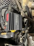
Good day All, I am new to the group, having just acquired a 1986 M1097. I've been working though a few bugs that it had before I could take it out on the road, but there is one that has me stumped because I dont understand the system well enough. It has 2 fresh (fully charged) batteries and a 200 amp dual voltage generator, a new voltage regulator and I believe all the wiring connected up correctly. My issue seems to be that I would have expected there to be 24 volts on the ignition/sense wire to excite the field and activate the regulator. Ive traced the wire back to the PCB (that seems like some sort of magic box) and I do not see any continuity through the box with the power turned off, but I expect that is because it only make contact when a relay is latched inside the box when powered up. I just don't see what I'm doing wrong and wondered if I could run a hot wire from the ignition circuit directly to the Voltage regulator sense to see it charge, or if doing that would blow up the (very expensive) PCB in the process. Any help would be appreciated as I'm at a loss!
 

Attachments

Mogman

Moderator
Staff member
Moderator
Steel Soldiers Supporter
6,611
9,212
113
Location
Papalote, TX
First check that the relay is latching up when the run switch is on, one way to confirm this is it also powers the heater blower so if the heater blower works when in run position then the relay is likely good, this relay has a history of failure.
Remember when troubleshooting (or any other time) you must wait at least 90 seconds every time the run switch is turned to the off position before returning to run or you can fry your glowplugs.
 

Mogman

Moderator
Staff member
Moderator
Steel Soldiers Supporter
6,611
9,212
113
Location
Papalote, TX
Also the wire tag for the IGN terminal on the reg should be 5A, you are correct that it needs 24V to excite the alt.
 

Mogman

Moderator
Staff member
Moderator
Steel Soldiers Supporter
6,611
9,212
113
Location
Papalote, TX
I also see the A/C terminal does not have a wire on it, that should be tag # 2A IIRC that tells the PCB that the engine is running but should not be keeping the alt from charging as it must be excited and charging before there will be AC voltage on that terminal
 

stphub

New member
7
0
1
Location
Arizona
First check that the relay is latching up when the run switch is on, one way to confirm this is it also powers the heater blower so if the heater blower works when in run position then the relay is likely good, this relay has a history of failure.
Remember when troubleshooting (or any other time) you must wait at least 90 seconds every time the run switch is turned to the off position before returning to run or you can fry your glowplugs.
My Heater blower does not run, but I thought that was another problem that I was going to address at a later date (not a lot of use for a heater in Arizona) but is the relay somewhere that I can access it, or is it inside the magic box??
 

Mogman

Moderator
Staff member
Moderator
Steel Soldiers Supporter
6,611
9,212
113
Location
Papalote, TX
BTW Welcome to the SS forums!!!
It is in the PCB, you can confirm that circuit breaker CB-2, wire tags #27 behind the inst. panel is not getting power before going into the PCB.
Careful inspection of the connectors on the PCB is also a good idea.
Can you hear the relay close when the switch is turned to run? you should also be able to hear it drop out when switched to off.
 

Mogman

Moderator
Staff member
Moderator
Steel Soldiers Supporter
6,611
9,212
113
Location
Papalote, TX
Does the wait light work normally? it should stay on for about 8 seconds when the engine is cold.
 

Mogman

Moderator
Staff member
Moderator
Steel Soldiers Supporter
6,611
9,212
113
Location
Papalote, TX
Also if you can post a picture of the label on the PCB, being a 1986 it is possible you have an obsolete (problem) PCB to begin with, does it have one or two harness connectors going to it from the engine side?
The original setup had a harness just for the glowplugs.
 
Last edited:

stphub

New member
7
0
1
Location
Arizona
First check that the relay is latching up when the run switch is on, one way to confirm this is it also powers the heater blower so if the heater blower works when in run position then the relay is likely good, this relay has a history of failure.
Remember when troubleshooting (or any other time) you must wait at least 90 seconds every time the run switch is turned to the off position before returning to run or you can fry your glowplugs.
I have been chasing round after the elusive 5A wire and just can't find it, I have also been taking some instruction from a chap on a Facebook forum and he appears to be very grumpy. my heater blower does not work and Im leaning towards the relay being bad. Is there any way to wire this without going through the control box, or even installing a more modern alternator??
 

Mogman

Moderator
Staff member
Moderator
Steel Soldiers Supporter
6,611
9,212
113
Location
Papalote, TX
Ohm out the one you have and see if it is going to pin F on the engine side PCB harness pin.
There are ways around everything (jury rig) but getting the actual problem fixed is always the best solution, you did not answer the other questions I asked about the PCB box.
 

stphub

New member
7
0
1
Location
Arizona
Ohm out the one you have and see if it is going to pin F on the engine side PCB harness pin.
There are ways around everything (jury rig) but getting the actual problem fixed is always the best solution, you did not answer the other questions I asked about the PCB box.
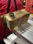
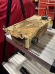
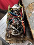
Yes I'm sorry for the late reply on this, but I was going through a whole load of things that Mr Grumpy had me doing on the FB forum. I can't hear the relay latch at all and so I have just taken it out of the truck. I have to tell you that it looks like it's been at the bottom of a pond for a few years, as you can see by these photos. Do I drill all the stem rivets out to get it apart?
 

Attachments

stphub

New member
7
0
1
Location
Arizona
Ok, so I found 5A. It was connected to a 14V output and was wrongly marked at the terminal as 68A. It has continuity to the F terminal and seems like a very large wire. I put the control box back in and started it to see if it was charging... sadly still no charge. Should I have battery voltage on that wire 5A when its in the run position??
 

Mogman

Moderator
Staff member
Moderator
Steel Soldiers Supporter
6,611
9,212
113
Location
Papalote, TX
I would say that PCB box is toast for sure, it probably looks the same on the inside as the outside, you may as well drill out the rivets and see.
Ol grumpy may be here also so... There are some folks with allot of knowledge that are a little short tempered when it comes to n newbies.
And yes you should have 24V on 5A, probably a good thing it does not as it may have burned out your regulator.
Again that PCB is likely no good, kinda purdy though
 

stphub

New member
7
0
1
Location
Arizona
Thanks for your help, I just checked and I have less than a volt on 5A and I would say that PCB is probably horrible inside. I'm going to take a look anyway, but can you suggest anywhere to get a good one for an old 6.2 1097??
 

Milcommoguy

Well-known member
Supporting Vendor
1,681
2,171
113
Location
Rosamond, CA
That's a Prestolite that has been resting next to the Titanic for the last 30 years.

Time for an up grade to something a bit more reliable.

I have a name in mind, CAMO
 

Mogman

Moderator
Staff member
Moderator
Steel Soldiers Supporter
6,611
9,212
113
Location
Papalote, TX
At least you have the "later" style PCB, makes it much easier to replace than the original one, there should be an extra hole in the body for the early style glowplug harness, probably where all the moisture came from, if you had the early style you would have needed to find and change the engine harness.
I see one of our vendors has chimed in that builds a manual control box that should be much more dependable in the long run, in any case the fix is not cheap.
 

Mogman

Moderator
Staff member
Moderator
Steel Soldiers Supporter
6,611
9,212
113
Location
Papalote, TX
Fortunately the harness connectors look nice and clean so you are probably good to go there..
 

stphub

New member
7
0
1
Location
Arizona
It looks pretty Nasty inside. The funny thing is that the cannon plugs and receptacles are great. The rest of the truck has virtually no corrosion, so this must have just had a steady drip of water on it over the years. So is the best place to buy one from CAMO, do they have a website??
 

Attachments

TOBASH

Father, Surgeon, Cantankerous Grouch
Steel Soldiers Supporter
Supporting Vendor
3,511
3,398
113
Location
Brooklyn, NY
Rebuild that unit. I posted schematics years ago. Not all my work, but I took the initiative with permission from others involved.

I can also help with a rebuilt one, as can others. I prefer if you DIY, but I have in stock. So do others.

 
Last edited:

Mogman

Moderator
Staff member
Moderator
Steel Soldiers Supporter
6,611
9,212
113
Location
Papalote, TX
It looks pretty Nasty inside. The funny thing is that the cannon plugs and receptacles are great. The rest of the truck has virtually no corrosion, so this must have just had a steady drip of water on it over the years. So is the best place to buy one from CAMO, do they have a website??
I cannot say as I have not had one to evaluate but there are plenty here that have.
 
Top
AdBlock Detected

We get it, advertisements are annoying!

Sure, ad-blocking software does a great job at blocking ads, but it also blocks useful features of our website like our supporting vendors. Their ads help keep Steel Soldiers going. Please consider disabling your ad blockers for the site. Thanks!

I've Disabled AdBlock
No Thanks