• Steel Soldiers now has a few new forums, read more about it at: New Munitions Forums!

  • Microsoft MSN, Live, Hotmail, Outlook email users may not be receiving emails. We are working to resolve this issue. Please add support@steelsoldiers.com to your trusted contacts.


M135 M211 2 speed transfer case mod

DUUANE

Active member
387
91
28
Location
Vancouver BC
Teardown Part 1

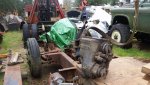
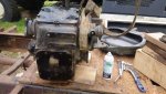
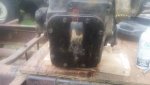
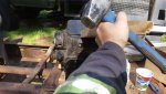
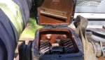
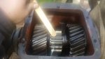
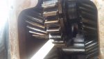
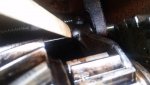
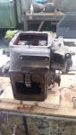
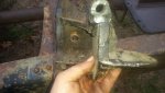
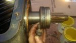
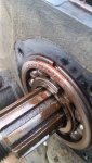
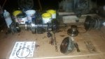
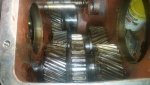
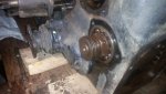
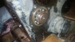
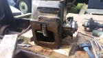
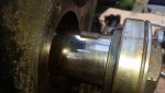
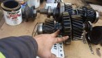
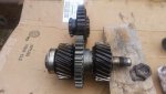
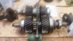
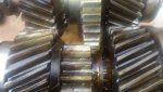
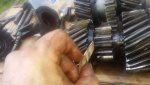
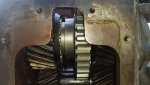
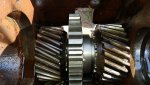
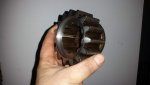
Well i got the spare tcase up on the "bench" for autopsy today...
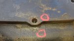
Make sure you punch mark covers for orientation and mark so you know where your marks are..find coffee cups/paint cans/ziplocs for your fasteners and washers and label them.
To get as far as i did today youll need;
1/2"
9/16"
5/8"
3/4"
1 -3/4"
2" sockets
the last 2 need to be a reasonably thin wall to fit into the drive flanges
15/16" wrench or deep socket
2" combination wrench
3/8" drive universal
2-6" 3/8" drive extensions.
Snapring pliers
Medium brass drift,lead or deadblow hammer.
Some means to hold the drive flanges..either fab something or i have a 48" pipe wrench that works nicely..grab it on the flat side of the flange to avoid damage.
If you dont have air or a cordless impact a couple of pieces (5 footers) as leverage helpers.
 

Attachments

Last edited:

DUUANE

Active member
387
91
28
Location
Vancouver BC
Teardown part 2

So here are the parts we are going for.

First pic is the input shaft sliding gear, we will remove it and WET grind it to 1.50"-1.4375" in length for clearance to prevent simultaneous engagement of high and low range.

Second pic is the pto drive gear.we will remove it,its bearing and snap ring, and the gear it rides on and replace it with gear 3659894 from the G508 GMC banjo transfer case.

Third pic is the input shaft shift fork..this will be removed clearanced on the forward side where the shift rail goes through it then reinstalled reversed on the shaft.
 

Attachments

Last edited:

DUUANE

Active member
387
91
28
Location
Vancouver BC
Teardown part 3

Now. (This is a step i would do while the case was still mounted in the chassis)
Mark drive flanges and seal housings for orientation and position.
remove cotter pins in the nuts that hold all the drive flanges on, get your pipes and your help and remove the nuts and flanges..(if your tcase is still in the truck,remove it now)..sample your beverage of choice when done.

Loosen the bolts but leave the seal housings in place and remove the input shaft shift fork lock bolt..access it through the pto opening with the 2 extensions and universal and a 1/2" socket.

Then remove the shift rail front housing that holds the detent balls it doesnt have to come all the way off at this point..just far enough to remove the shift fork from the shaft.
Remove the fork,screw in the lock bolt to keep track of it.

Next remove the input shaft front bearing snap ring..if there is gasket material left on the case it will have to be removed to get the snapring out.

My case had no brake assembly so remove yours if you havnt already.

The rear seal housing/park brake anchor bracket is next. There are 2 adjuster bolts on either side of the output shaft threaded into the rear seal housing there is a 3/4" jam nut on the outside..back those out first. The the adjusters are a 1/2" head..remove them both..see pics 2 and 3. Once those are out you will be able to remove the remaining 9/16" head bolts and slide the housing off..pick 4 shows how they preload the outputshaft bearing.

Now take your brass drift/lead/deadblow hammer and tap the output gear/shaft rearward in the case and evenly side to side a hair at a time and it will slide out of the back of the case.

The forward part of the input shaft ,input shaft sliding gear and driven gear can be used as kind of a slide hammer..engage the sliding gear in the driven gear and use the assembly on the shaft to gently knock the input shaft front bearing out of the case..once the bearing is out you can remove the forward input shaft assembly.
 

Attachments

Last edited:

DUUANE

Active member
387
91
28
Location
Vancouver BC
Teardown part 4

So now your case should look about like pic 1

Next remove the speedometer driven gear from the idler shaft front cover.. 15/16" wrench or deep socket. Remove the cover. There was a groove for a snap ring but no snap ring in this case..i will check the TM and see if it was supposed to be there.( The TM shows no snap ring on the front bearing that i can see). There is a snap ring on the idler shaft rear bearing, leave it in place for now.
The nuts are 2" both ends. This is as far as i got tonight. An impact would be nice for these. But a wrench to hold and a ratchet will probably do.i am going to try and slide the shaft forward out of the case to avoid disturbing the spedo drive gear if i can. While im looking into the snap ring ill see what the TM says about the intermediate shaft removal.

See you tomorrow..cup of tea in hand.
 

Attachments

Last edited:

DUUANE

Active member
387
91
28
Location
Vancouver BC
Teardown part 5

Here we are again..so pic one is where we left off last time..after cheating and peeking at the TM ..the speedo drive gear does have to come off. You can use a split bearing puller or i modified a pitman arm puller to work..be careful not to warp the gear or damage teeth ,a little heat from a map torch may help....make note of which way it goes on(mark it) pull the gear off.. There is a small woodruff key in the rear of the shaft that hast to come out to the rear of the case..so get yourself your flange tool(or giant pipe wrench) and a couple of overweight friends a small brass drift to wedge between the teeth of the input shaft driven gear and idler shaft drive gear and remove the idler shaft front retaining nut and lock washer.

Once thats done get a brass or lead hammer( block of wood and 3 lb hammer) and tap the idler shaft rearward in the case..the gears will stay put but the shaft and rear bearing will move out of the case.leave the snapring on the bearing.(pic 2)

*** put something under the rear of the case to catch the woodruff key i mentioned earlier..it will fall out of the rear of the case as you drive the shaft rearward..dont let it fall into the abyss***(pic 3)

Once you pull the shaft out you can go after the idler shaft gears..there is a spacer between the front gear and the front bearing..let it drop down into the case as you pull the gears out the top. Hold the input ,clutch/pto gear and output gear together as you lift ..there are only the gear dogs holding the 3 pieces together..dont drop them on your toes. Retrieve the spacer from the bottom of the case.

Now we are at pic 4 im pointing to the assembly that will be removed and replaced by gear 3659894

Pic 5 is a shot of the new gear assembled on the shaft with the old pto/clutch gear assembly above it.

Pic 6 is a group shot to illustrate the new gear in relation to the input shaft with the sliding gear in high range.

Pic 7 is a shot to give you an idea how much material needs to be removed from the input shaft sliding gear to pervent simultaneous engagement of high and low range. The overlapped portion of the slider vs 3659894 looks to be about 1/4".

Pic 8 im pointing to the side of the gear i think the material will be removed from.

All in all i am 99% sure this is a done deal..there will be clearancing in the case to do as 3659894 sits a little rearward of where the pto drive gear was. And ther will be clearancing of the input shaft shift fork as well as new detent ball grooves in the shift rail.

I have a busy month coming up..2 major refits to do at work so i may only be able to poke at this for a while but i will update as i go.

Ladies and gentlemen we have a 2 spd transfer case conversion for the M135/M211 trucks!

Now we can repower with confidence.

We as a group need to start negotiation with an axle shaft supplier to begin planning an axle shaft upgrade..they will be the new fuse in the driveline.

I'm really happy about this so far..and im thankful for all the people that helped in getting us to here.

I hope you all had a Happy Easter.
 

Attachments

Last edited:

Ashley P

Member
67
54
18
Location
W. KY
Happy Easter to you!

Fantastic posts with great info! Thank you for the effort.

Edit to add: Did I miss the price/source for the gear?
 
Last edited:

DUUANE

Active member
387
91
28
Location
Vancouver BC
Thanks there will be more to come..on modifying the case as well as i believe i will have to make a new cover..
I bought my gears from a place in italy..cost me $50USD ea and $110USD shipping to Vancouver Island. There are other sources but i went this way because they were N.O.S. parts..
Pm me for info..dont want to break any rules.

Oh and the shipping was for 2 gears as i have 2 cases to do.
 
Last edited:

DUUANE

Active member
387
91
28
Location
Vancouver BC
Case modifications part 1

Well i managed to get the tractor all rigged up and loaded on the tilt n slide and out the door at a reasonable hour so i had some time to mess with the tcase project a bit.

You can see from the pics how the opening in the case will have to be enlarged..
There is a corresponding bump in the cover that gives clearance for the gear. I dont think there is enough meat there to just shave some more room and its a casting..
So my plan of attack will be to;
1: Mark out the relief cut in the case opening with a generous radius in the corners to avoid creating stress risers that could lead to a crack.
2: make a new cover from a chunk of plate, fab a pop up secion for gear clearance.
3: use the new cover as a guide to drill and tap a couple extra bolt holes in the case to ensure the cover will seal as we will loose one existing hole.

I'm going to try and make time to get by the machine shop to have the input shaft sliding gear reworked this week. As well as make a plan for the shift rod.
I have to find 1 gear and the upper output shaft bearing.
The gear i need is the front lower rear output shaft gear (labled X in the TM) The one in this case is a little crusty.. funny that it and the upper output shaft bearing were the only casualties..everything else is shiny and smooth as butter.

Thats all i have for now..
Hope you all have a great week.
 

Attachments

Last edited:

gentrysgarage

Active member
553
118
43
Location
Lost Angels, CA
You know I have been so engrossed in the 2 speed transfer case details the I didn't even see the forest for the trees...how about a yard tour?!? I see so many interesting things!
 

DUUANE

Active member
387
91
28
Location
Vancouver BC
Let me get a chance to get the pressure washer out..Haha..the giant fir trees here drop a 1/4" blanket of pollen a day on everything here..once the dew sets on it its a layer of green glue for the darn needles to stick to..it litterally takes 1 week for something to look like its been here a hundred years..very frustrating.
I cant wait to move to the new location.
No more land of the lost..
 

DUUANE

Active member
387
91
28
Location
Vancouver BC
My machinist got the input shaft sliding gear today..it is extremely hard material. I didnt get a before picture regrettably, but we are going to start with milling off 1/4" from the end opposite where the shift fork grabs it . There is a recess cut into the end of the input shaft sliding gear for the thrust washer or whatever it is that the input shaft driven gear loads up against. We are duplicating that profile (- ) 1/4" overall.

More soon..pics too..

Oh and the shift rails look like regular 3/4" round bar..so rather than modify the old one im gonna try some cold rolled round stock and make a new one.
 
Last edited:

DUUANE

Active member
387
91
28
Location
Vancouver BC
Input shaft sliding gear modification

Good news..i got the sliding gear back from the machinist today..he did a beautiful job. He said it was hard as glass..and advised to take it to someone with skill and to not rush or things will go sideways.

So as stated in an earlier post we knocked off 1/4" from the end opposite the annulus for the shift fork.
I wont likely have time to put it together to see for a week or two..and i want to get the case modifications done so i can leave the idler shaft in place while i get the gear fitted, just in case we need to remove additional material.( from the sliding gear)

More to come.

I hope everyone is enjoying the shift into spring.
 

Attachments

Last edited:

DUUANE

Active member
387
91
28
Location
Vancouver BC
Unfortunately not yet..back to back ferry repairs are eating all my time..may have some time to play around the 15th of june or so..
 

DUUANE

Active member
387
91
28
Location
Vancouver BC
The view from my office, well its not really an office..its the south end of the drydock, my home away from home, away from home. Looking toward the downtown core of Vancouver.
 

Attachments

Last edited:

DUUANE

Active member
387
91
28
Location
Vancouver BC
Well..the boat is still drying in the dock..both cpp hubs off and in the shop,one rudder down, one shaft out and in the shop.
I may have a day off by the end of the month..if i get lucky.
Dreaming of working on stuff with wheels..and o.d. paint
 

Ashley P

Member
67
54
18
Location
W. KY
What kinda boat/engine/stuff are you working on? I'm near the confluence of the Ohio and Mississippi rivers, barge repairs are common. This tells you how much I know about it: Somebody trucks large props by my house, they come back very shiny. lol
 

DUUANE

Active member
387
91
28
Location
Vancouver BC
Im a mechanic/engine fitter at the largest drydock on the mainland west coast of canada..we do overhaul and major refit to all the ferrys and most of the barge work, cruise ships and super yachts around here. We are scaling up for LNG refits as well so that is kinda exciting.
Todays task..we rigged,lifted and pulled a 34 ton 65ft long shaft and hub up into the boat..1mm of clearance to the bearing..using 5 and 10ton chainblocks..just taking a lunch break now.
 
Last edited:

DUUANE

Active member
387
91
28
Location
Vancouver BC
I specialize in CPP's (controllable pitch propellors) and related systems..they are a multi piece propellor controlled by oil pressure..the hubs on this boat were 14 tons each..(x2) and each hub has 4 blades about 5000lbs each..held on by 8 M80 stainless bolts torqued to 17,500 lb/ft.
They are an interesting jigsaw puzzle of parts. I build bow and stern thruster units as well but they are like toys compared to the main propulsion. Polishing propellors is a skilled job..its tough to make the right pattern and keep it even over a crazy shape like that..artisan work.
This is a great job. But im getting older and will have to hand the 25lb hammers off to the next generation soon..i still have a great swing..but i pay for it.
Today i pulled up a 4 ton rudder stock...through a $30k set of seals..fit the bearing, mounted the split retainers, drove the bearing up the taper to the specified height, locktight and lockwired all the clamshell allen bolts. Cleaned and mounted the tiller arm(steeering yoke) and aligned it with my dissassembly marks on the rudder stock. Landed and mounted the pilgrim nut on the end of the rudder stock completing the basic assembly of the upper steering parts.
Next step is to hook a hydraulic intensifier to the tiller arm body and a air hydraulic foot pump to the pilgrim nut, bring the pressure in the nut up to 1500-2000psi and hold. Then we intensify the tiller arm to about 40,000psi..wait 10-15 mins or so for the oil to reach the bottom of the rifling on the inside..once that happens we have achieved 2 things..the tiller arm bore has stretched about .004-.005" and the arm is now floating on a continuious film of oil..then with dial guages mounted and zero'd we use the pilgrim nut to drive the tiller arm down the taper on the rudder stock about 12mm (immagine a huge nut that is also a hydraulic cylinder, thats a pilgrim nut) once we reach the specified depth..we release the intensifier pressure and wait 30 mins or so for the tiller arm to return to its origional size..then release the pilgrim nut pressure. Wind it up on the rudder stock threads a bit..jack the ram back into the nut(its single acting) spin it down so it contacts the tiller arm.
Check your dissassembly marks to be sure you drove it down far enough..weld keepers and we can move on to soaking the steering ram pins in liquid nitrogen..
 

rustystud

Well-known member
9,071
2,387
113
Location
Woodinville, Washington
I specialize in CPP's (controllable pitch propellors) and related systems..they are a multi piece propellor controlled by oil pressure..the hubs on this boat were 14 tons each..(x2) and each hub has 4 blades about 5000lbs each..held on by 8 M80 stainless bolts torqued to 17,500 lb/ft.
They are an interesting jigsaw puzzle of parts. I build bow and stern thruster units as well but they are like toys compared to the main propulsion. Polishing propellors is a skilled job..its tough to make the right pattern and keep it even over a crazy shape like that..artisan work.
This is a great job. But im getting older and will have to hand the 25lb hammers off to the next generation soon..i still have a great swing..but i pay for it.
Today i pulled up a 4 ton rudder stock...through a $30k set of seals..fit the bearing, mounted the split retainers, drove the bearing up the taper to the specified height, locktight and lockwired all the clamshell allen bolts. Cleaned and mounted the tiller arm(steeering yoke) and aligned it with my dissassembly marks on the rudder stock. Landed and mounted the pilgrim nut on the end of the rudder stock completing the basic assembly of the upper steering parts.
Next step is to hook a hydraulic intensifier to the tiller arm body and a air hydraulic foot pump to the pilgrim nut, bring the pressure in the nut up to 1500-2000psi and hold. Then we intensify the tiller arm to about 40,000psi..wait 10-15 mins or so for the oil to reach the bottom of the rifling on the inside..once that happens we have achieved 2 things..the tiller arm bore has stretched about .004-.005" and the arm is now floating on a continuious film of oil..then with dial guages mounted and zero'd we use the pilgrim nut to drive the tiller arm down the taper on the rudder stock about 12mm (immagine a huge nut that is also a hydraulic cylinder, thats a pilgrim nut) once we reach the specified depth..we release the intensifier pressure and wait 30 mins or so for the tiller arm to return to its origional size..then release the pilgrim nut pressure. Wind it up on the rudder stock threads a bit..jack the ram back into the nut(its single acting) spin it down so it contacts the tiller arm.
Check your dissassembly marks to be sure you drove it down far enough..weld keepers and we can move on to soaking the steering ram pins in liquid nitrogen..
That sounds so cool !!!
I'm really looking forward to meeting you and talking about your job !
 
Top
AdBlock Detected

We get it, advertisements are annoying!

Sure, ad-blocking software does a great job at blocking ads, but it also blocks useful features of our website like our supporting vendors. Their ads help keep Steel Soldiers going. Please consider disabling your ad blockers for the site. Thanks!

I've Disabled AdBlock
No Thanks