HanksDeuce
Well-known member
- 1,087
- 264
- 83
- Location
- Prairieville, LA
It seems that I enjoyed taking the factory multi-fuel engine and Spicer 3053A transmission out of the deuce, but I forgot to take a few key measurements before I started the job.
I am looking to see if someone could help me determine the following measurements on a factory deuce:
1) park deuce on level ground
2) Measure the following items:
a. angle of deuce engine - put angle finder on top of engine
b. angle of Spicer 3053A transmission - on top or flat spot on bottom
c. angle of Spicer 3053A output yoke
d. angle of transmission to transfer case driveshaft (aka intermediate shaft)
e. angle of transfer case input yoke
f. angle of transfer case - on top or flat spot on bottom
g. if intermediate shaft is completely horizontal then maybe it is offset to one side of the chassis (favors one frame rail or the other)
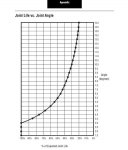
These measurements will help me determine the angle required on the intermediate shaft. My driveline guy down the street recommends needle bearings get at least 2 degrees of angle so they spin in the u-joints. I would like to run my Cummins 6BT between 0-5 degrees down. The freightliner bus that was the donor vehicle for my project had a 5 degree downward angle for the 6BT engine/tranny.
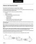
I have attached a picture for reference. Keep in mind the rear diff is now the xfer case in this instance. And that I need the engine angle too. It should be the same as the tranny, but someone may surprise us.
Thanks in advance!
Attachments
-
4.2 KB Views: 17
Last edited:


