• Steel Soldiers now has a few new forums, read more about it at: New Munitions Forums!

  • Microsoft MSN, Live, Hotmail, Outlook email users may not be receiving emails. We are working to resolve this issue. Please add support@steelsoldiers.com to your trusted contacts.


M37 temperature indication problem

Lenny

New member
91
0
0
Location
NH
I have a 1953 M37; I recently had to remove the throttle cable from the dashboard and after repairs were completed re install it. It was very tight working and after cramming it all back together I took a test drive. About 2 miles up the road I noticed that the temperature gage was reading 260 degrees. I pulled over, shut it down and fully expected to see steam pouring out of the radiator, but it was obvious that it was not over heating, and it had definitely not been operating at 260 degrees. So I drove it back to my house and parked it. I tried turning the ignition on and off a few times over the next few minutes and each time the temperature gage deflected to 260 or basically pegged. This morning however it did not deflect at all cold. I haven't tried starting it today yet.

In looking at the wiring diagram the circuit is very simple. +24 volts is fed to one side of the gage. The other side of the gage goes to a thermistor or temperature sensor which is mounted on the block under the oil filter. That thermistor must change resistance proportional to the temperature it is exposed to. The other side of the sensor goes to ground.

So before I pull the instrument panel again I was wondering if anyone had any information on the electrical characteristics of the gage, (meter), and the sensor. For instance with the gage on the bench what is the voltage necessary to deflect the gage to 260 degrees, or full scale? I'm thinking it has to be 24 volts. And also does anyone have or has anyone plotted the temperature vs. resistance curve for the thermistor? These two bits of information would really help me a lot in diagnosing this problem. Thanks, Lenny
 

ez8

Member
42
2
8
Location
Indiana, USA
Since your original post makes it sound like your gauge was working before hand, I doubt that the gauge itself suddenly quit working.
My bet is that while you were digging around in the dash you bumped something or inadverntantly created a ground or otherwise interrupted the circuit which is causing the incorrect reading. I did this a few days ago with my oil pressure gauge while I was trying to get the fuel gauge to work. The wiring harnesses in these trucks, especially a '53 are getting fragile in their old age and sometimes the insulation will separate.

The easiest trouble shooting you can do is just start checking continuity along the circuit. Grab your multimeter or testing light and dig in.
 

Lenny

New member
91
0
0
Location
NH
I know. I've been waiting for the last two days for some nice weather. It's been so cold and rainy here it is just hard to think about working in the yard. I even had to light the wood stove this morning. And we had close to 90 degrees here just the other day. Thats New Hampshire for you.

Yeah I agree with your assessment of the gage not causing this. I figure assuming that it is good theoretically the only thing that would cause the gage to peg would have to be a short to ground on the low side of the gage. Maybe could have happened when I "crammed" the dash back together. That possible shorted line would be the line out to the sensor. I think I'll borrow my son's laser thermometer and try to investigate that first. Thanks for your suggestions. Best regards Lenny
 

mdainsd

Member
198
25
18
Location
San Diego, CA
The temp gauge terminal that runs to the engine sensor, is the closest wire to the throttle cable you were fooling with. If the wiring is old, it is probably right at the gauge where you could have mashed the wire. If the insulation is brittle it will flake right off and short to the metal shell connectors. If I remember right, shorting the sensor wire gives full scale reading. Also if your wiring is that brittle, it is time to address it before something more serious than a temp gauge malfunction occurs. Serious like a cab fire.
 

m38inmaine

Well-known member
2,090
44
48
Location
Maine USA
Sounds like it could be a faulty sending unit, you can test it with a multi meter set to ohms. Should be about 3000 ohms cold, 1200 ohms @ 160 degrees, 917 ohms @ 180 degrees and 450 ohms @ 240 degrees. Disconnect the wire from the sending unit, attach one lead to the pin on the sending unit and the other to ground. I would check it cold and at normal operating temp.
 

Lenny

New member
91
0
0
Location
NH
I was able to get back into this problem over the past weekend. First let me say thank you to everyone for your input. i would also like to particularly thank SST ret. for providing me with the temperature sender resistance values V temperature information. Having that information proved to be invaluable and it helped me to determine where the problem was.

The first thing that I did was read the resistance of the sender cold. It read 2600 ohms. That was pretty close to the 3000 ohms that I was looking for. I connected the sender back up and noted that the gage was reading nothing with either the ignition on or off. I then started the truck, and ran it for awhile, letting it heat up while observing the gage. It slowly moved up to about a 140 - 160 reading, stayed there, and after a few minutes of holding steady, to my utter amazement it proceeded to slowly creep up and bury itself all the way to the right at 260 degrees. I felt the rear of the block in the vicinity of the temperature sensor. It was uncomfortably warm but certainly not steaming at 260 degrees as the gage was indicating.

I shut the ignition off and the turned it on again for a moment and unlike the previous cold start response of no reading the gage moved up to about a 120 - 140 indication and then slowly moved all the way up to 260. So it was starting to become apparent that the problem was occurring as the engine reached operation temperature. I disconnected and read the sensor resistance again. it was 1600 ohms. So the sender seemed to be functioning, but the gage appeared to be responding in a non linear way. Extrapolating from the information previously given me I put the temperature at about 120 - 140 degrees. So I decided to pull the gage. My intention was to set up a mock test situation on the bench using a variable DC power supply along with variable known resistances to simulate the gage in the truck at various temperatures. It seemed simple enough.

I had the two wires off the gage and as I removed it from the dash I inadvertently twisted it upside down. That's when I noticed something very strange. The needle sort of "fell down" to 260 degrees indication. Twisting it back caused it to once again "fall back" to about 20 percent of full scale indication. I repeated this several times and each time watched the needle "flop" back and forth between full scale and 20 percent deflection. I was going to order a gage but noting the price of them I first went on the Internet to do a little reading. I found this article on M series gages and it mentioned the importance of having a good ground. I had been assuming that the gage, having two terminals was simply a conventional DC voltmeter. In fact the schematic of the truck wiring shows +24 volts applied to one side of the gage, with the other side of the gage connected to the sender and then the internal sensor is in series with this and internally connected to ground. That all seems apparent and is certainly simple enough, however there is some type of connection to ground within the gage that is not shown on the schematic. I never considered that "ground" would be of any concern, but was I ever wrong. After providing a good ground for the gage the problem was resolved. The gage may still "flop" when turned upside down but I don't plan on doing much upside down driving in the future so I believe that it would be a moot point. I should have remembered that it doesn't seem to matter, civilian or military automotive schematics just plain suck. You never get to see everything, and of course you should never assume anything.

The interesting thing here, (and I had forgotten this) was that I experienced a similar problem with a newly acquired M35A2 two years ago. That drove me nuts also. There again a ground problem on the temperature gage was responsible for a false high temperature indication.

It kind of reminds me of the guy who goes to the psychiatrist and says "doc, you gotta help me. My brother thinks he's a chicken". So the psychiatrist says "well can't you explain to him that this is irrational and such things are not possible"? So the man says "I would but I need the eggs".....

Don't ever assume anything.
Lenny

https://www.dodgepowerwagon.com/best/m37_gauge_resistance.php
 

mdainsd

Member
198
25
18
Location
San Diego, CA
Good job!

1) Yes they "flop"
2) The ground scheme is flaky at best, it relies on too many points of contact, metal to metal, with rust, paint and who knows what else gumming up the works. Any of the M vehicles that I have had that act up gauge wise immediately get another "star" harness on the back of the panel. It picks up one mounting screw on each gauge with an internal tooth ring terminal and a longer lead with the same type terminal that I hook to the cab behind the dash panel. They work so much better that way.
 

Lenny

New member
91
0
0
Location
NH
So I've been wondering. An automotive gage is essentially a DC voltmeter. A conventional DC voltmeter has two terminals, a positive and a negative. There is never any connection to chassis or a "ground" of any sort. So what could be inside these gages that is tied to ground?

Yesterday I found an old M series dashboard panel among st my junk. I don't know where I got this thing from or why I saved it. It was a total rust bomb and the gages were all smashed. So I decided to perform an "autopsy" on the temperature gage. (I hope this wasn't one of the ones with the radium paint on it). I learned a few things. For one, these gages were definitely not meant to be repaired. I had to essentially destroy the case to get the guts out, but it did answer the original question. Inside, there are two coils wired in series. The end of one coil goes to the positive terminal of the gage and the other end goes to the negative terminal. You would think that was all there was to it however the midpoint of the two coils goes to chassis ground. I'm not sure about this but perhaps this was a way to balance the circuit. In any event that's the answer to "what's in the box". Lenny
 

mdainsd

Member
198
25
18
Location
San Diego, CA
Yes, temp, fuel and pressure are a balanced coil set up. One coil is a reference as such and the second coil is hooked to a resistive element to register change. This is done so the readings do not change with voltage supply change. They all require two isolated terminals and a ground connection to the battery and the sender to indicate properly.

Voltmeters are a one terminal device with a ground. Ammeters are two terminal and do not need a ground reference.
 

Lenny

New member
91
0
0
Location
NH
This makes a lot of sense. I did notice when this was presenting itself that it was mostly when the engine was running and the supply was 29 volts. So this is how the voltage to the gage was regulated. I hadn't even thought of indication differences between 24 and 29 volts. In the system I envisioned they would have been horrendous. Pretty ingenious for 1953. My Lionel train set was also manufactured in 1953. It's also all electro mechanical. It's impressive to realize what those old time engineers could do with the paltry resources that THEY had. Lenny
 

mdainsd

Member
198
25
18
Location
San Diego, CA
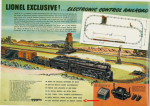
I have lots of old Lionels myself. it is amazing how cleaver they were. In the thirties you could set up an elaborate layout with switch tracks interconnected so that the route would always be changing. Yours being '53 is it the "electronic" set?
 

Lenny

New member
91
0
0
Location
NH
Nothing in 1953 was electronic. It was all relays and switches. My equipment is all original as it came from the factory. Probably the only "electronics" in a household back then was the radio or TV, (if they had one). Lenny
 

mdainsd

Member
198
25
18
Location
San Diego, CA
You should research it. It existed and it came out in 1948. It was electronic with a transmitter and a receiver in each car and two in the locomotive.

blobid0.png
 

Noah long

New member
1
0
1
Location
Dallas
Sounds like it could be a faulty sending unit, you can test it with a multi meter set to ohms. Should be about 3000 ohms cold, 1200 ohms @ 160 degrees, 917 ohms @ 180 degrees and 450 ohms @ 240 degrees. Disconnect the wire from the sending unit, attach one lead to the pin on the sending unit and the other to ground. I would check it cold and at normal operating temp.
Hey, I checked with a multimeter and my engine was warm and it showed, 1070 ohms. However, my engine temp sensor is all the way on the hot side at 240. The engine is not too hot to the touch. Also, I’m pretty sure I don’t have a bad ground. Does this mean my temp gauge is broken?
 

mdevill

New member
7
0
1
Location
Lafayette, LA
Hey, I checked with a multimeter and my engine was warm and it showed, 1070 ohms. However, my engine temp sensor is all the way on the hot side at 240. The engine is not too hot to the touch. Also, I’m pretty sure I don’t have a bad ground. Does this mean my temp gauge is broken?
I found this old post today and it explains why both temp gauges I checked don't indicate properly. I didn't have either of them grounded. In both of my tests, the gauges didn't move off the low side. I did check resistance between the sending unit and ground but, at the time, didn't know what the readings should have been. I know I read about 1200 ohms. I'm going to check the sending unit again to verify the resistance value then connect the gauges properly (with a known ground) and find out if either gauge works.

For your situation, I would suggest ensuring a proper ground or at least verifying the existing ground with an ohm meter (very close to zero ohms). Also confirm your supply voltage at the gauge. If you confirm those two connections and either rely on your readings from the sending unit or re-check them again, I would think your meter is suspect. Before purchasing another, I would suggest lightly tapping on it. The parts/pieces are old and the gauge is not the most smoothly operating thing. Something may have jammed it and tapping it may jar the obstruction loose.
 

frank8003

In Memorial
In Memorial
6,426
4,973
113
Location
Ft. Lauderdale, Florida
Mostly I never saw a temperature gauge of any flavor depict the real temperature within 15%. On the subs they are rather accurate. Late model in aircraft are really
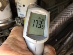
Good but in a on-the-wheels/tracked vehicle they are ALWAYS suspect and wrong. Use your temperature heat gun first. Jump to no illogical conclusions,
"The data support No conclusions as Yet"
Mine is an antique but you get the idea.
Seach for Handheld Laser IR Infrared Thermometer Gun.
Fluke 59's are really good but I have no money, have to use what i got.
 

Attachments

Last edited:

Floridianson

Well-known member
Steel Soldiers Supporter
7,390
2,434
113
Location
Interlachen Fl.
Has anyone switched out to mechanical water and oil gages. The oil seems easy enough but I would like to do water to just do not know if the head port is deep enough for the sending unit. I am not a purest so different gages do not bother me. Tanks
 

mdevill

New member
7
0
1
Location
Lafayette, LA
Has anyone switched out to mechanical water and oil gages. The oil seems easy enough but I would like to do water to just do not know if the head port is deep enough for the sending unit. I am not a purest so different gages do not bother me. Tanks
I replaced the electronic oil gauge with a cheap mechanical one because I didn't trust the sending unit or the gauge. At some point, I will go back to the original. Switching to the new gauge was easy. Remove the sending unit then connect fittings and tube to where the sending unit came off of. Route the tubing into the dash and into the gauge. I have not done similar to the water temp gauge.
 
Top
AdBlock Detected

We get it, advertisements are annoying!

Sure, ad-blocking software does a great job at blocking ads, but it also blocks useful features of our website like our supporting vendors. Their ads help keep Steel Soldiers going. Please consider disabling your ad blockers for the site. Thanks!

I've Disabled AdBlock
No Thanks